


Operating Instructions – Electronic Motor DRC.-..-DAC
51
5
Cable routing and shielding
Electrical Installation
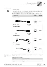
5.5.3
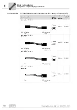
Notes on cable routing and shielding
Note the following when routing and shielding the cables:
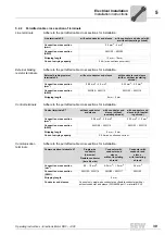
• Cable selection
– You can use unshielded connection cables for the power leads (3 x AC 400 V –
AC 500 V + PE).
– Control cables must be shielded. Route them separately from cables that emit
interference (e.g. control cables of solenoid valves, motor leads).
– Use shielded cables for the optional external braking resistor.
– The shield must have good EMC properties (high shield attenuation) and must not
be used for mechanical protection of the cable.
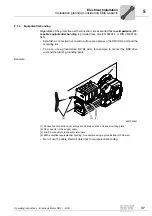
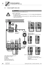
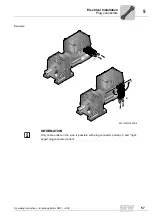
• Cable shield – external braking resistor
– Connect the cable shield of the cable for an external braking resistor to the metal
housing of the unit using the shield clamps of the installation material kit. To do
so, strip off the cable sheath around the shield connection surface.
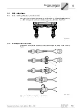
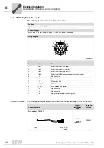
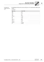
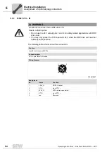
• The AS-Interface data cable and sensors are generally connected using plug
connectors.
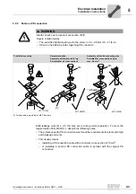
• Cable shielding – Control cables
– Connect the shields of the control cables to the metal housing of the unit using
the shield clamps of the installation material kit. To do so, strip off the cable
sheath around the shield connection surface.
– As an alternative, you can use optionally available EMC cable glands to connect
the shield of control cables, see chapter "EMC cable glands".


