


144
Operating Instructions – Electronic Motor DRC.-..-DAC
8
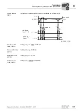
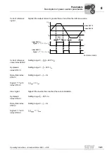
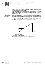
Description of power section parameters
Parameters
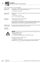
Power section parameters \ unit functions \ error monitoring
The following responses can be programmed:
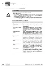
WARNING
Risk of injury if the drive unit starts up automatically.
Severe or fatal injuries.
• Error messages can be automatically reset depending on the programmed error
response, i.e. the drive units receive the current process output data from the
controller again as soon as the error is corrected.
If, for safety reasons, this is not permitted for the driven machine, disconnect the
unit from the supply system before correcting the error.
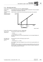
Response
Description
[0] NO RESPONSE
The error is not displayed, and there is no error response. The
signaled error is ignored.
[1] DISPLAY ONLY
The error is displayed and the error output is set (if programmed). The
unit performs no other error responses. The error can be reset
(fieldbus, auto reset).
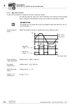
[2] OUTPUT STAGE INHIBIT /
LOCKED
The inverter switches off immediately and issues an error message.
The output stage is inhibited and the brake (if installed) is applied. The
ready signal is revoked and the error output is set, if programmed. A
restart is only possible after an error reset during which the inverter is
reinitialized.
[3] EMERGENCY STOP /
LOCKED
The drive is braked along the set emergency stop ramp t14. Once the
stop speed is reached, the output stage is inhibited and the brake (if
installed) is applied. The error is signaled immediately. The ready
signal is revoked and the error output is set, if programmed. A restart
is only possible after an error reset during which the inverter is reinitial-
ized.
[4] STOP / LOCKED
The drive is braked along the set stop ramp t13. Once the stop speed
is reached, the output stage is inhibited and the brake (if installed) is
applied. The error is signaled immediately. The ready signal is revoked
and the error output is set, if programmed. A restart is only possible
after an error reset during which the inverter is reinitialized.
[5] OUTPUT STAGE INHIBIT /
WAITING
The inverter switches off immediately and issues an error message.
The output stage is inhibited and the brake (if installed) is applied. The
error is signaled via the terminal, if programmed. The ready signal is
removed. The drive restarts without unit re-initialization if the error is
rectified by an internal procedure or by an error reset.
[6] EMERGENCY STOP /
WAITING
The drive is braked along the set emergency stop ramp t14. Once the
stop speed is reached, the output stage is inhibited and the brake (if
installed) is applied. The error is signaled immediately. The error is
signaled via the terminal, if programmed. The ready signal is removed.
The drive restarts without unit re-initialization if the error is rectified by
an internal procedure or by an error reset.
[7] STOP / WAITING
The drive is braked along the set stop ramp t13. Once the stop speed
is reached, the output stage is inhibited and the brake (if installed) is
applied. The error is signaled immediately. The error is signaled via the
terminal, if programmed. The ready signal is removed. The drive
restarts without unit re-initialization if the error is rectified by an internal
procedure or by an error reset.
00
I


