


Manual – DFD11B DeviceNet Fieldbus Interface
55
6
Process data exchange
DeviceNet Characteristics
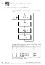
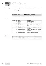
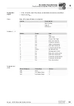
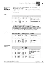
The following table shows the data range of the bit-strobe request message which rep-
resents the allocation of stations (= station address) to data bits.
Example: For example, the participant with station address (MAC-ID) 16 only processes
bit 0 in data byte 2.
Timeout
response with bit-
strobe I/O
The timeout is triggered by the DFD11B option. The timeout interval must be set by the
master after the connection has been established. The DeviceNet specification refers to
an 'expected packet rate' rather than a timeout interval in this case. The expected packet
rate is calculated on the basis of the timeout interval using the following formula:
t
Timeout_BitStrobe_I/O
= 4 x t
Expected_Packet_Rate_BitStrobe_I/O
It can be set using connection object class 5, instance 3, attribute 9. The range of values
runs from 0 ms to 65535 ms in 5 ms steps.
If a timeout occurs for the bit-strobe I/O messages, this connection type enters timeout
status. Incoming bit-strobe I/O messages are no longer accepted. The timeout is not for-
warded to the inverter.
The timeout reset takes place as follows:
• via DeviceNet with the reset service of the connection object (class 0x05, instance
0x03, undetermined attribute)
• by interrupting the connection
• via reset service of the identity object (class 0x01, instance 0x01, undetermined at-
tribute)
STOP!
The BIO LED on the front of the DFD11B option can be used for distinguishing between
the timeout triggered by the bit-strobe telegram and a real timeout in the connection. It
remains continuously green if the timeout is triggered by the bit-strobe telegram.
If the BIO LED flashes red, this means there is a timeout in the bit-strobe connection
and no more bit-strobe telegrams are accepted. Each participant that has received this
bit-strobe I/O message responds with its current process input data. The length of the
process input data corresponds to the process data length for the polled I/O connec-
tion. The process input data length can be up to four process data.
Byte off-
set
7
6
5
4
3
2
1
0
0
ID 7
ID 6
ID 5
ID 4
ID 3
ID 2
ID 1
ID 0
1
ID 15
ID 14
ID 13
ID 12
ID 11
ID 10
ID 9
ID 8
2
ID 23
ID 22
ID 21
ID 20
ID 19
ID 18
ID 17
ID 16
3
ID 31
ID 30
ID 29
ID 28
ID 27
ID 26
ID 25
ID 24
4
ID 39
ID 38
ID 37
ID 36
ID 35
ID 34
ID 33
ID 32
5
ID 47
ID 46
ID 45
ID 44
ID 43
ID 42
ID 41
ID 40
6
ID 55
ID 54
ID 53
ID 52
ID 51
ID 50
ID 49
ID 48
7
ID 63
ID 62
ID 61
ID 60
ID 59
ID 58
ID 57
ID 56
0
0
I


