


18
Manual – DFD11B DeviceNet Fieldbus Interface
4
Shielding and routing bus cables
Assembly and Installation
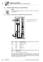
4.6
Shielding and routing bus cables
The DeviceNet interface supports RS-485 communications protocol and requires cable
type A specified for DeviceNet in accordance with EN 50170 as shielded, twisted-pair
cable for the physical connection.
Correct shielding of the bus cable attenuates electrical interference that may occur in
industrial environments. The following measures ensure the best possible shielding:
• Manually tighten the mounting screws on the connectors, modules, and equipotential
bonding conductors.
• Apply the shielding of the bus cable on both ends over a large surface.
• Route signal and bus cables in separate cable ducts. Do not route them parallel to
power cables (motor leads).
• Use metallic, grounded cable racks in industrial environments.
• Route the signal cable and the corresponding equipotential bonding close to each
other using the shortest possible route.
• Avoid using plug connectors to extend bus cables.
• Route the bus cables closely along existing grounding surfaces.
4.7
Bus termination
In order to avoid disruptions in the bus system due to reflections, each DeviceNet seg-
ment must be terminated with 120
Ω
bus terminating resistors at the first and last phys-
ical participant. Connect the bus terminating resistor between connections 2 and 4 of the
bus plug.
STOP!
In case of fluctuations in the ground potential, a compensating current may flow via the
bilaterally connected shield that is also connected to the protective earth (PE). Make
sure you supply adequate equipotential bonding according in accordance with relevant
VDE regulations in such a case.


