


Manual – DFD11B DeviceNet Fieldbus Interface
27
5
Configuring PLC and master (DeviceNet scanner)
Project Planning and Startup
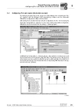
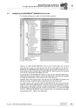
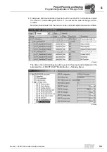
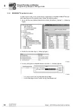
After adding the DFD11B gateway to the scanlist, the number of polled I/O Bytes must
be set to 2
×
number of PD (e. g. number of PD = 6
×
number of polled input-Bytes = 12
and output-Bytes = 12) via 'Edit I/O Parameters'. When the DeviceNet configuration is
saved and downloaded into the scanner, RSNetWorx can be closed.
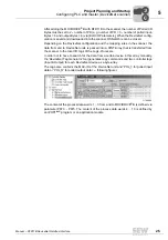
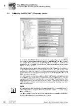
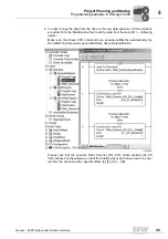
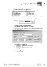
Depending on the DeviceNet configuration and the mapping rules in the scanner, the
data from and to DeviceNet units is packed into a DINT-Array that is transferred from
the scanner to the local I/O tags of the Logix-Processor.
In order not to have to search for the data from a certain device in this array manually,
the 'DeviceNet Tag Generator' tool generates copy commands and two controller tags
(Input & Output) for each DeviceNet device as a byte-array.
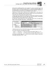
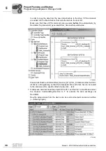
The tag-name contains the MAC-ID of the DeviceNet unit and 'POL_I' for polled input
data or 'POL_O' for polled output data (
→
following figure).
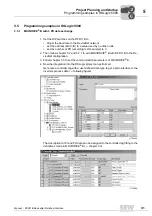
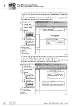
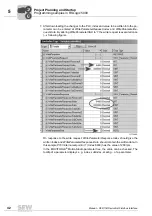
In this Byte arrays from and to the DFD11B gateway the data is transferred to the drives
connected to the SBus of this gateway as follows:
• Byte 0 ... 5 contain PD 1 ... 3 of the drive with the lowest SBus address (e. g. 1)
• Byte 6 ... 11 contain PD 1 ... 3 of the drive with the next higher SBus address (e. g. 2)
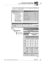
The content of process data word 1 ... 3 from and to the drives is defined in each drive
individually via parameter P870 ... P875.
11751AXX
0
0
I


