


20
MOVIDRIVE
®
PROFIBUS DFP11A
3
The PROFIBUS-DP
Interface
For a detailed description of the drive inverter's timeout behavior, please refer to the Fieldbus Com-
munications Profile Manual.
Important!
Parameter P819 Fieldbus Timeout can only be set through the timeout period which is configured
in the DP master for the whole DP system. Manual setting of this parameter with the MX_SHELL
user interface has no effect, any setting would be overwritten when PROFIBUS-DP is started up the
next time.
3.4
Diagnostic Data
Station diagnosis of the MOVIDRIVE
®
drive inverter can be performed using the DP service
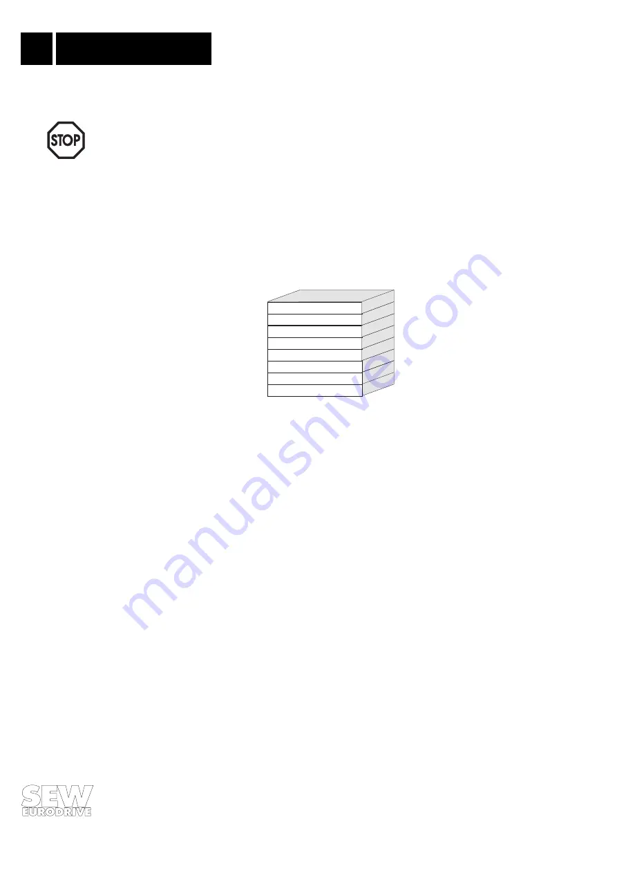
DDLM_Slave_Diag. The drive inverter also supports unit-related diagnosis. Fig. 18 shows the
structure of the diagnostic data.
00136AEN
Fig. 18: Structure of the diagnostic data for the MOVIDRIVE
®
Octets 1-7 contain the diagnostic information according to DIN E 19245 Part 3. As the header of
the unit-related diagnostic data, a value of 2 in octet 7 indicates that the unit-related diagnostics are
2 bytes in length (incl. header). If there is a fault on the drive inverter, octet 8 will also contain the
fault code (only then will external diagnosis be possible).
Important!
The unit-related diagnostic information is only updated every 800 ms approx. This means that a
fault message may not be output for 800 ms after the fault occurs. A much faster and simpler
method of detecting faults can be implemented using status word 1 of the MOVIDRIVE
®
drive
inverter.
Octet 1:
Octet 2:
Octet 3:
Octet 4:
Octet 5:
Octet 6:
Octet 7:
Octet 8:
station status 1
station status 2
station status 3
DP master address
Ident Number (high)
Ident Number (low)
Header
Unit-related diagnose