


MOVIDRIVE
®
PROFIBUS DFP11A
13
Assembly / Installation
Instructions
2
2.10 Commissioning the Drive Inverter
After installing the PROFIBUS option pcb the MOVIDRIVE
®
drive inverter can be immediately
parameterized via the PROFIBUS system without any further adjustment. This means, for example,
that after switching on the drive inverter, all parameters can be downloaded directly from the
higher-level automation system.
To control the drive inverter via PROFIBUS, however, it must first be switched to control source
(P101) and setpoint source (P100) = FIELDBUS. With the FIELDBUS parameter setting, the drive
inverter is programmed to accept setpoints from the PROFIBUS. The MOVIDRIVE
®
drive inverter
now responds to process data sent from the higher-level automation system.
The activation of the FIELDBUS control and setpoint sources is signalled to the higher-level control
system by the Fieldbus Mode Active bit in the status word.
For safety reasons the drive inverter must also be enabled via the terminals to permit control via
the fieldbus system. The terminals are therefore to be wired or programmed in such a way that the
drive inverter is enabled via the input terminals. The easiest way of enabling the drive inverter via
the terminals is, for example, to connect input terminal DIØØ (function /CONTROLLER INHIBIT) to
a +24 V signal and program input terminals DIXØ1 .. DIØ3 to NO FUNCTION. An example of the
commissioning procedure for the MOVIDRIVE
®
drive inverter with a fieldbus interface is given
below.
Commissioning procedure for the MOVIDRIVE
®
drive inverter
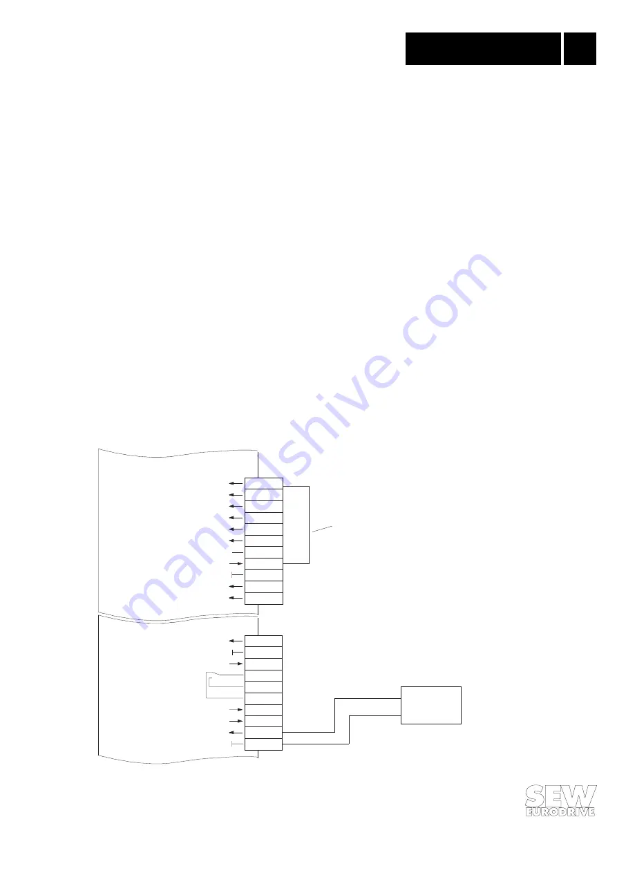
1.
Enable the output stage via the terminals.
Apply a +24 V signal on input terminal DIØØ / X13.1 (function /CONTROLLER INHIBIT) (e.g.
via jumper).
01234AEN
Fig. 9: Enabling the output stage via jumper
+
-
X13:
DI00
DI01
DI02
DI03
DI04
DI05
DCOM
VO24
DGND
ST11
ST12
TF1
DGND
DB00
DO01-C
DO01-NO
DO01-NC
DO02
VO24
VI24
DGND
X10:
Control head
External 24 V
supply
/Controller inhibit
No function
No function
No function
No function
No function
Reference X13:DI00 5
+ 24 V
Reference potential binary signals
RS-485+
RS-485-
TF input
Reference potential binary signals
/Brake
Relay contact
Relay NO
Relay NC
/Fault
+ 24 V
+24 V (external)
Reference potential binary signals
Use this jumper to
enable the output stage
via the terminals