


70
Operating Instructions – Explosion-Proof CMP Synchronous Servomotors
11
Power connector assembly
Appendix
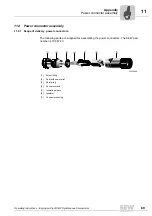
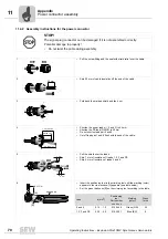
11.4.2 Assembly instructions for the power connector
STOP!
The signal plug connector can be damaged if it is not assembled correctly.
Potential damage to property!
• Do not twist the cable during assembly.
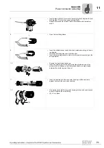
1
•
Pull the screw fitting and the seal with strain relief over the cable.
2
•
Strip 59 mm of cable insulation off the end of the cable.
3
•
Fold back the braided shield and fan it out.
4
•
Shorten the power leads (1, 2 and 3) to 44 mm.
•
Shorten the PE lead (GN/YE) to 45 mm.
•
Do not shorten lead pair 5 and 6.
•
Cut off lead pair 7 and 8 flush with the end of the cable.
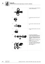
5
•
Pull the shield over the leads.
•
Strip 7 mm of insulation off leads 1, 2, 3 and PE.
•
Strip 5 mm of insulation of leads 5 and 6.
6
•
Insert the positioning tool in the crimping tool until the marking (color)
appears in the view window [A] appears (see table below).
•
Set the press thickness [B] on the crimping tool according to the table.
Lead
a [mm
2
]
Positioning
tool
Part number
xxx xxx x
Marking
(color)
Press
force
5 and 6
0.14 ... 1.0
019 244 9
Green (GN)
24
1, 2, 3 and PE
0.35 ... 4.0
019 245 7
Blue (BU)
6
59 mm
PE (45 mm)
1,2,3 (44 mm)
5,6 (59 mm)
7 mm
5 mm
xxx xxx xx
[B]
[A]
BU / GN
Summary of Contents for CMP40
Page 2: ...SEW EURODRIVE Driving the world ...
Page 86: ......


