


Manual – XFE24A EtherCAT Fieldbus Interface
37
7
EtherCAT introduction
Motion Control via EtherCAT
In motion control applications, positioning travel with target position and travel parame-
ters such as speed and ramp time is administered in the motion controller – that is usu-
ally the higher-level controller. From the calculated path curve, a setpoint speed (
→
sec.
"7.2.1") or setpoint position (
→
sec. "7.2.2") is tranmitted to the servo inverter in short
intervals. The servo inverter then sets this setpoint speed or position and reports the cur-
rent position back. The motion controller knows by itself when the positioning command
has been executed.
Since the higher-level controller transmits the setpoints cyclically, the acceleration and
deceleration ramps are also calculated in this controller. No ramp function integrated
into the drive is used here.
Clock
synchronism
For each control cycle, the controller reads in the position actual value and calculates
the current speed (dx/dt) and probably other information such as acceleration, jerk, etc,
from the position difference (dx) and the time difference (dt) of the previous control in-
terval.
The time slices of the controller, the bus transmission and the internal processing cycle
of the servo inverter and of external encoders, if applicable, must be synchronized to
one another.
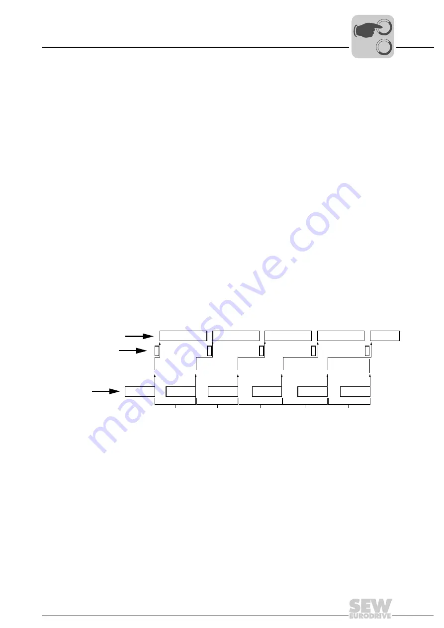
Example
This example is to demonstrate how aliasing effects can occur if controller, bus, servo
inverter or encoder are not clock-synchronous (
→
following figure).
• Control time slice of the controller: 5 ms
• Bus clock pulse: 5 ms, synchronous to the controller
• Processing time in the servo inverter: 5 ms, not synchronous
Since in this example, the servo inverter or encoder and the controller are not synchro-
nized, the time slices will slowly drift apart because their quartz oscillators are not ideal.
This can lead to jumps in the transmitted position value.
61480AXX
Figure 14: Creation of aliasing effects
1
2
3
4
5
dtS
dtG
dx
dx
dx
dx
dx
[A]
[B]
[C]
[A]
Control interval dt
S
[C]
Time slice of servo inverter or encoder dt
G
[B]
Bus cycle
dx
Position difference (covered distance)
0
0
I
Summary of Contents for 1821 2492
Page 2: ...SEW EURODRIVE Driving the world...
Page 66: ......