


36
Manual – XFE24A EtherCAT Fieldbus Interface
7
EtherCAT introduction
Motion Control via EtherCAT
7
Motion Control via EtherCAT
This chapter contains information about the EtherCAT functions that enable clock syn-
chronous operation of MOVIAXIS
®
connected to an EtherCAT master, which is neces-
sary for motion control applications.
7.1
EtherCAT introduction
This section describes the functions and terms used for clock synchronous operation of
SEW servo inverters on EtherCAT. Comprehensive, detailed technical information
about EtherCAT is available from the EtherCAT user organization, e.g. at
www.EtherCAT.org, and from the manufacturers of EtherCAT master systems.
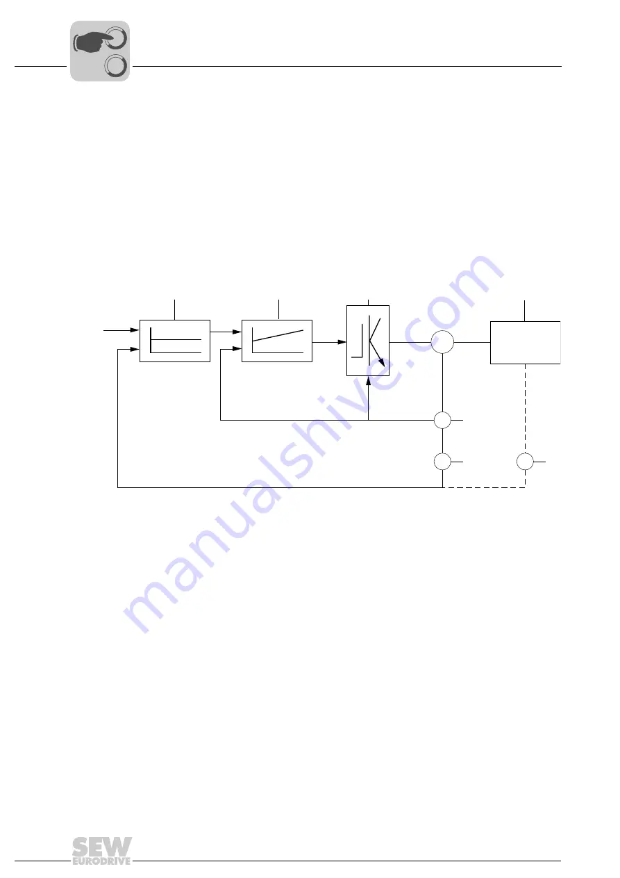
Based on the cascade control common in drive technology, the principal mechanisms
for motion control applications are described here.
A position setpoint (x
ref
) is the starting point. Using the position actual value (x
act
), the
position controller [1] calculates a speed setpoint (v
ref
). The speed controller [2] uses
speed setpoint and actual value to calculate the torque setpoint (t
ref
), which generates
a torque in the motor supplied by the servo inverter output stage [3]. Depending on the
counter-torque caused by the driven machine [4], the motor runs with a certain speed
(measured by encoder [5]). Depending on the motor speed, a position change occurs,
which is detected by a position encoder [5] on the motor.
Depending on the application, the control loops for torque, speed or position can now be
closed in the servo inverter or in the higher-level controller. MOVIAXIS
®
can take over
all control loops including position control. In this case, positioning travel can only be
performed when a setpoint position is transferred to the servo inverter (e.g. "Bus Posi-
tioning" application module). The current position and, once the positioning command
has been executed, a "ready message" is sent to the controller.
61477AXX
M
V
X
X
[1]
[2]
[3]
[4]
t
ref
v
ref
v
act
x
act
x
ref
[5]
[5]
[6]
x
ref
Position setpoint
[1]
Position controller
x
act
Position actual value
[2]
Speed controller
v
ref
Speed setpoint
[3]
Output stage of the servo inverter
v
act
Actual speed value
[4]
Driven machine (load)
t
ref
Torque setpoint
[5]
Encoder (V = speed; X = position)
[6]
Optional encoder
0
0
I
Summary of Contents for 1821 2492
Page 2: ...SEW EURODRIVE Driving the world...
Page 66: ......