SEW-Eurodrive 1821 2492 Manual Download Page 23

Manual – XFE24A EtherCAT Fieldbus Interface 

23

5

Settings on the MOVIAXIS® servo inverter using the example of single-axis

EtherCAT Configuration and Startup

Manual settings

Manual setting of the communication and PDO configurations:
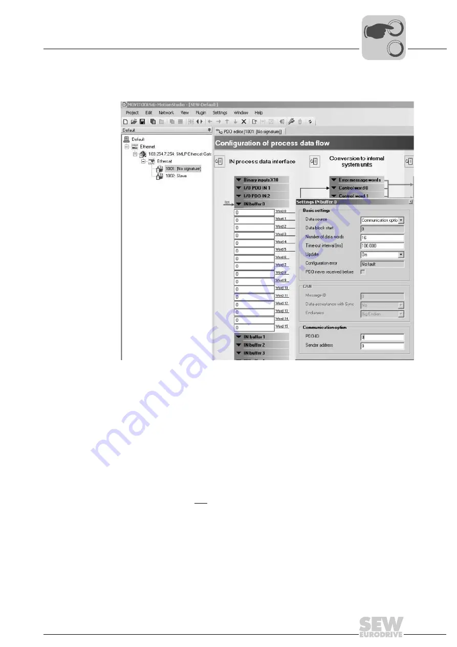
• Start the PDO Editor.

• For operation with an EtherCAT bus system, a free "IN buffer" (e.g. IN buffer 0) must

be configured:
• Number of data words: 

16

 for firmware status 21


1 ... 16

 for firmware status 22 and higher

EtherCAT with MOVIAXIS

®

 always transfers 16 data words.

"Number of data words" determines how many data words are used of the 16 that
are transferred.
• Time-out interval
Here, you can set the monitoring time for the "IN buffer". If the process data commu-
nication exceeds the set time, error message 67 "Error PDO timeout" is issued. 
Setting range 0 ... 100....100000 ms (0 ms corresponds to deactivated, standard is
100 ms).
• Update: 

On

Updating the process data.

11658AXX

Figure 8: Manual settings

0

0

I

Summary of Contents for 1821 2492

Page 1: ...Gearmotors Industrial Gear Units Drive Electronics Drive Automation Services MOVIAXIS MX Multi Axis Servo Inverter XFE24A EtherCAT Fieldbus Interface Manual Edition 08 2007 11550619 EN...

Page 2: ...SEW EURODRIVE Driving the world...

Page 3: ...mation 10 3 3 3 Cyclical data exchange via EtherCAT 10 3 3 4 Acyclical data exchange via EtherCAT 10 3 3 5 Configuration of the EtherCAT option card 10 3 3 6 Monitoring functions 11 3 3 7 Diagnostics...

Page 4: ...e 39 7 1 2 Settings for Velocity mode speed interface 40 7 1 3 Position setpoint interface Position mode 44 7 1 4 Settings for Position mode 45 7 2 Settings in the EtherCAT master 47 7 2 1 Settings fo...

Page 5: ...le consequence s if disregarded Measure s to avoid the hazard Symbol Signal Word Meaning Consequences if disregarded Example General hazard Specific hazard e g electric shock HAZARD Imminent hazard Se...

Page 6: ...to persons or damage to equipment or property resulting from non observance of the op erating instructions In such cases any liability for defects is excluded 1 4 Integral part of the product This ma...

Page 7: ...ing covers without authorization improper use as well as incorrect installation or operation may result in severe injuries to persons or damage to property Refer to the documentation for more informat...

Page 8: ...as shielding grounding ar rangement of filters and routing of lines in the documentation of the multi axis servo in verters Always observe these notes even with multi axis servo inverters bearing the...

Page 9: ...manual The MOVIAXIS Multi Axis Servo Inverter project planning manual contains a list of all parameters of the servo inverter that can be read or written via the various communica tion interfaces suc...

Page 10: ...WRITE services are introduced in line with the EtherCAT specifica tion They are transmitted during normal cyclical operation along with the messages without affecting the performance of the process da...

Page 11: ...or example con veyor belt As the range of functions for the control terminals is also guaranteed in field bus mode you can continue to implement rapid stop concepts using the terminals of the servo dr...

Page 12: ...n the nameplate The component XFE24A has already been installed at the factory For information on the option card slots refer to the MOVIAXIS Multi Axis Servo Inverter operat ing instructions 62190axx...

Page 13: ...ectors The EtherCAT master is connected via EtherCAT slaves if necessary with a shielded twisted pair cable to X30IN RJ45 Other EtherCAT units are then connected vie X31OUT RJ45 54174axx Figure 3 Pin...

Page 14: ...g Connect the shielding in the connector over a wide surface area Apply the shielding of the bus cables on both ends Route signal and bus cables in separate cable ducts Do not route them parallel to p...

Page 15: ...no follow up unit is connected to an EtherCAT unit this is automatically detected 4 5 Setting the station address The address of EtherCAT units from SEW EURODRIVE cannot be set at the unit These unit...

Page 16: ...state Flickering green INITIALISATION or BOOTSTRAP The XFE24 option is starting up and has not yet reached the INIT state The XFE24A option is in the BOOTSTRAP state The firmware is being down loaded...

Page 17: ...display flickers once very shortly followed by an off phase 58095AXX Flashing The display switches between on and off in common mode with a frequency of 2 5 Hz 200 ms switched on 200 ms switched off...

Page 18: ...ieldbus interface 1 Install copy the XML file according to the requirements of your project planning soft ware Once the file has been installed correctly the unit appears next to the slave stations un...

Page 19: ...For communication with MOVIAXIS via XFE24A there is a PDO type available for cy clical process input and output data OutputData1 Standard 16 PO Static PDO with 16 cyclical process output data words wh...

Page 20: ...Figure 5 Assignment of standard process output data for OutputData1 PO 1 PO 2 PO 3 PO 4 PO 5 PO12 PO13 PO14 PO15 PO 16 acycl Mailbox Communication cycl OutputData1 Standard 16 PO Index Subindex Offse...

Page 21: ...ard process input data for PDO InputData1 Index Subindex Offset in the PDO Name Data type Size in bytes 3E1C 0hex 15900 0dez 0 0 PI1 UINT 2 3E1D 0hex 15901 0dez 2 0 PI2 UINT 3E1E 0hex 15902 0dez 4 0 P...

Page 22: ...is described in detail in the MOVIAXIS Multi Axis Servo Inverter operating instructions All communication parameter and the PDO configuration are set using the Single Axis Positioning Technology Edito...

Page 23: ...data words 16 for firmware status 21 1 16 for firmware status 22 and higher EtherCAT with MOVIAXIS always transfers 16 data words Number of data words determines how many data words are used of the 1...

Page 24: ...procedure for complete startup of the MOVIAXIS servo inverter with EtherCAT link is described in the MOVIAXIS Multi Axis Servo Inverter operating instructions For safety reasons you must also enable...

Page 25: ...r Data EtherCAT Master SEW Drive SEW Drive FCS I O Drive 1 Drive 2 Drive 3 For more information about controlling via the process data channel in particular re garding the configuration of the control...

Page 26: ...e TwinCAT subdirectory IO EtherCAT you can add MOVIAXIS to the EtherCAT structure in the offline mode via Append box following figure In online mode i e connected to the EtherCAT line you can use the...

Page 27: ...data words to the PLC program or write data into them for manual testing as shown in the following figure First mark the process output data PO1 In the following window select the Online tab page Cli...

Page 28: ...ication Basic settings Communication option to set the monitoring time for the EtherCAT option card XFE24A If this monitoring time is exceed ed during the process data configuration an error message i...

Page 29: ...o response 1 Display only 2 Output stage inhibit locked 3 Stop at emergency stop limit locked 5 Output stage inhibit waiting 6 Stop at emergency stop limit waiting 8 Stop at application limit waiting...

Page 30: ...ting the function For In progress message or error message For timeout monitoring For reporting errors during the execution MOVITOOLS MotionStudio can access all unit functions via VoE services Vendor...

Page 31: ...ad nSubIndex Subindex of the parameter to be read pDstBuf Pointer to the data range in which the read parameters are to be stored cbBufLen Maximum memory size for parameters to be read in byte bExecut...

Page 32: ...sNetID Specification of the Net ID of the EtherCAT master nSlaveAddr EtherCAT address of the SEW unit from which the data is read nIndex Index of the parameter to be read nSubIndex Subindex of the par...

Page 33: ...ntegrated in TwinCAT as follows SEW parameter always have a data length of 4 Byte 1DWord For scaling and a more detailed description refer to the MOVIAXIS Project Planning Manual In the above example...

Page 34: ...es a more exact classification of the error type 6 3 3 Error code The error code element 1 Byte allows for a more detailed identification of the error cause within the error class For Error class 8 Ot...

Page 35: ...PPED_OBJECTS_EXCEED_PDO Number of mapped objects is to large for PDO 0x06040043 6 4 43 PARAM_IS_INCOMPATIBLE Data format is not compatible with index 0x06040047 6 4 47 INTERNAL_DEVICE_INCOMPATIBILITY...

Page 36: ...d actual value to calculate the torque setpoint tref which generates a torque in the motor supplied by the servo inverter output stage 3 Depending on the counter torque caused by the driven machine 4...

Page 37: ...alculates the current speed dx dt and probably other information such as acceleration jerk etc from the position difference dx and the time difference dt of the previous control in terval The time sli...

Page 38: ...n trigger error messages The problem described above caused by discreet sampling in different systems will usu ally only be a problem in motion control applications when the cycle time of the controll...

Page 39: ...cification and lag error monitoring are realized in the higher level controller and are not tasks of MOVIAXIS To prevent unwanted high acceleration values for larger control intervals 1 ms the speed s...

Page 40: ...AT Fieldbus Interface 7 EtherCAT introduction Motion Control via EtherCAT 7 1 2 Settings for Velocity mode speed interface IN process data 11663AXX Figure 16 IN process data 11719AEN Figure 17 Control...

Page 41: ...rocess data according the above example using drag drop Control word 0 settings Make the sample settings in control word 0 according to Figure 17 IN process data settings Set the IN process data accor...

Page 42: ...onfiguration of the FCB06 inter polated speed Set the cycle time of your EtherCAT controller in the controller setpoint cycle parameter e g 1 ms In addition to that the source for the speed setpoint m...

Page 43: ...t data correspond to the factory setting OUT buffer 0 links Then establish links from status word 0 and OUT process data to the Out buffer 0 using drag drop 11666AXX Figure 20 OUT process data The uni...

Page 44: ...monitoring of permitted travel ranges or limit switches can be performed in the servo inverter Whether the settings of a load dependent ramp specification and lag er ror monitoring in the servo inver...

Page 45: ...therCAT Fieldbus Interface 45 7 EtherCAT introduction Motion Control via EtherCAT 7 1 4 Settings for Position mode IN process data 11667AXX Figure 22 IN process data 11720AEN Figure 23 Control word 0...

Page 46: ...assignment of control word 0 differs from the process data link for Velocity mode Control word 0 settings Make the sample settings in control word 0 according to Figure 23 IN process data settings Se...

Page 47: ...2 Settings in the EtherCAT master For time slice synchronization you must activate the function Distributed Clock The bus cycle of the MOVIAXIS must correspond exactly to that of the external control...

Page 48: ...e resolution is set during startup 7 3 Example TwinCAT Configuringclock synchronous operation Make the settings shown in the following figures For clock synchronous operation select the DC for synchro...

Page 49: ...dog time in the Value field NC axis configuration Then the NC axis is configured following figure On the Settings tab page select the Standard option in the Axis Type field and the system unit e g in...

Page 50: ...nder Axis x_Drive Enter the following values in the Analog tab page following figure MOVIAXIS factory settings for speed The setpoint speed Reference Velocity maximum motor speed 6 is given with the c...

Page 51: ...ontrol via EtherCAT Finally the setpoint speed and the actual position of the drive are linked to the NC axis The control and status word 1 is controlled by teh PLC task according to the description i...

Page 52: ...otionStudio are integrated into the Ether CAT telegrams via the mailbox gateway in the EtherCAT master The feedback of the drives is transferred by the XFE24A in the same way to the mailbox gateway an...

Page 53: ...OVITOOLS MotionStudio is to be op erated from a different PC the EtherCAT master requires a second Ethernet interface which is connected via LAN to the PC on which MOVITOOLS MotionStudio is installed...

Page 54: ...ram of Beckhoff the above settings look as follows 8 6 Network settings on the engineering PC If MOVITOOLS MotionStudio runs on the EtherCAT master no network settings need to be made If the EtherCAT...

Page 55: ...x in the selection window Click on the Prop erties button The Properties TCP connection window will open Tick the Use this IP address checkbox and enter the following following figure 2 Variant Defini...

Page 56: ...nication paths at the same time When you start MOVITOOLS MotionStudio the SEW communication server is also started and an additional icon will appear in the Windows status bar 8 7 2 Procedure 4 steps...

Page 57: ...way in the EtherCAT master 4 In the Settings Options menu call up the Online mode menu item Ensure that the Never execute automatically 1 option is ticked in the Cyclic accessibility field 61937AXX 1...

Page 58: ...can Operating MOVITOOLS MotionStudio via EtherCAT 8 8 Automatic search for connected units unit scan After pressing function key F5 or the Online scan symbol all configured com munication channels are...

Page 59: ...ant to operate and activate the plug in menu using the right mouse button 8 10 Known problems when operating MOVITOOLS MotionStudio Check the following points if problems occur during configuration Is...

Page 60: ...Step 2 How does the RUN LED respond Is the bus connector connected to the master servo inverter NO A YES How does the Link activity LED on the XFE24A react OFF A ON Is the connection of the servo inve...

Page 61: ...IONAL state A boot error was detected Boot the XFE24A option If the ERR LED continues to flicker the XFE24A option is faulty Flashes red twice Example 1 RUN LED lights up green slave is in OPERATIONAL...

Page 62: ...e RUN LED lights up green once slave is in SAFE OPERATIONAL state An invalid configuration has occurred Correct the configuration error and then start the bus in the master Switch the slave to OPERATI...

Page 63: ...ion technology 2 RJ45 8x8 modular jack Bus termination Not integrated because bus termination is automatically activated OSI Layer EtherNet II Station address Setting via EtherCAT master Name of the X...

Page 64: ...lbox gateway configuration 54 Monitoring functions 11 Motion control via EtherCAT 36 Example TwinCAT 48 Introduction 36 Position mode 44 Settings in the EtherCAT master 47 Velocity mode 39 MOVITOOLS M...

Page 65: ...gs 41 IN buffer 0 links 41 IN process data 40 IN process data settings 41 OUT buffer 0 links 43 OUT process data 43 SEW communication server 56 Single axis positioning Manual settings 23 Settings with...

Page 66: ......

Page 67: ...SEW EURODRIVE Driving the world...

Page 68: ...g quality that reduces the cost and complexity of daily operations With a global presence that offers responsive and reliable solutions Anywhere With innovative technology that solves tomorrow s probl...

Reviews: