


System design
Doc. # 177/52701
Rev. 3.3
5-11
Key switch fuse F2
Use a fuse rated for the larger of: A) the sum of the drive currents plus 1A for internal circuits,
and B) the capacitor pre-charge circuit. In the following example there are two contactors each
drawing 2 A:
Device
Current
A
Line contactor
2 A
Pump contactor
2 A
Gen4 control circuits
1 A
B Pre-charge circuit
7 A
Fuse choice: 7A.
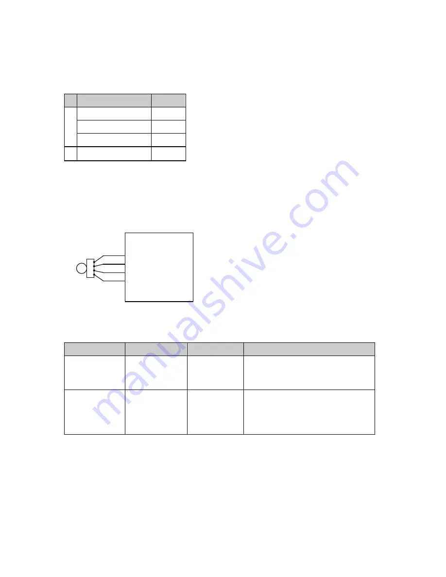
Motor speed sensor (encoder)
A 4-wire connection is provided for open-collector or current-source quadrature pulse encoder
devices (software configurable). These types of encoder are optimized for accurate speed
measurement, required for efficient control of induction motors.
E
AB Quadrature
Pulse Encoder
(pin numbering
may vary)
3
4
1
2
26
14
25
15
Gen4 Controller
+5/10V Supply
0 V
encoder A
encoder B
Figure 16 - Sample wiring for an AB quadrature speed encoder
You can use the following types of encoder, or equivalents:
Type
Output
Supply
Specification
Bearing Type
(SKF and FAG)
Open collector
5 to 24 V DC
64 and 80 pulses per revolution
Dual quadrature outputs
Output low = 0 V (nominal)
HED Type
(Thalheim)
Constant current 10 V nominal
80 pulses per revolution
Dual quadrature outputs
Output low = 7 mA
Output high = 14 mA
Single channel encoders (without the encoder B connection) are also supported. However, when
using this type of encoder, torque output is limited to the forward direction only. While these
encoders can be used for belt drive or pump motors, the torque output limitation makes these
unsuitable for traction applications.
The number of encoder pulses per revolutions (
n
) and the maximum motor speed (
N
) are related
to, and limited by, the maximum frequency of the encoder signal (
f
max
). The following table shows
the maximum motor speed for a given encoder on a 4-pole motor.
Summary of Contents for Gen4
Page 1: ...Gen4 Applications Reference Manual Document no 177 52701 Rev 3 3 ...
Page 9: ...Chapter 1 Introduction ...
Page 13: ...Chapter 2 About the Gen4 ...
Page 25: ...Chapter 3 Installation ...
Page 45: ...Chapter 4 Specification ...
Page 53: ...Specification Doc 177 52701 Rev 3 3 4 9 Dimensions Size 2 models Size 4 models ...
Page 54: ...4 10 Size 6 models ...
Page 55: ...Chapter 5 System design ...
Page 60: ...5 6 Single traction wiring diagram Figure 13 Single traction wiring diagram ...
Page 63: ...System design Doc 177 52701 Rev 3 3 5 9 On board fuse See On board fuse mounting on page 3 11 ...
Page 64: ...5 10 Figure 15 Dual traction wiring diagram ...
Page 70: ......
Page 71: ...Chapter 6 Configuration ...
Page 110: ......
Page 111: ...Chapter 7 Monitoring Gen4 ...
Page 122: ......