background image

stepIM 

Technical Training Manual 

26 

6.


Leave the switch off, and select the 

Inversion

 option to invert the polarity 

of the input: 


The LED graphic turns green. 


The drive becomes enabled. 

Note that the LED on the Demo Kit input switch does not change states 

when Inversion is selected. 

7.


Clear the 

Inversion

 option. 

Exercise - Input as Position Limit Switch 

An input can be defined as a limit switch. 

1.


Make sure switch 

IN 2

 and switch 

IN 3

 are 

off

, and the drive is enabled. 

2.


In the Digital I/Os screen, set Input 2 Mode to 

Positive Limit Switch

Set Input 3 to 

Negative Limit Switch.


3.


Go to the 

Motion 

screen, select operation mode 

Profile Position

, and 

reenable the drive. 

4.


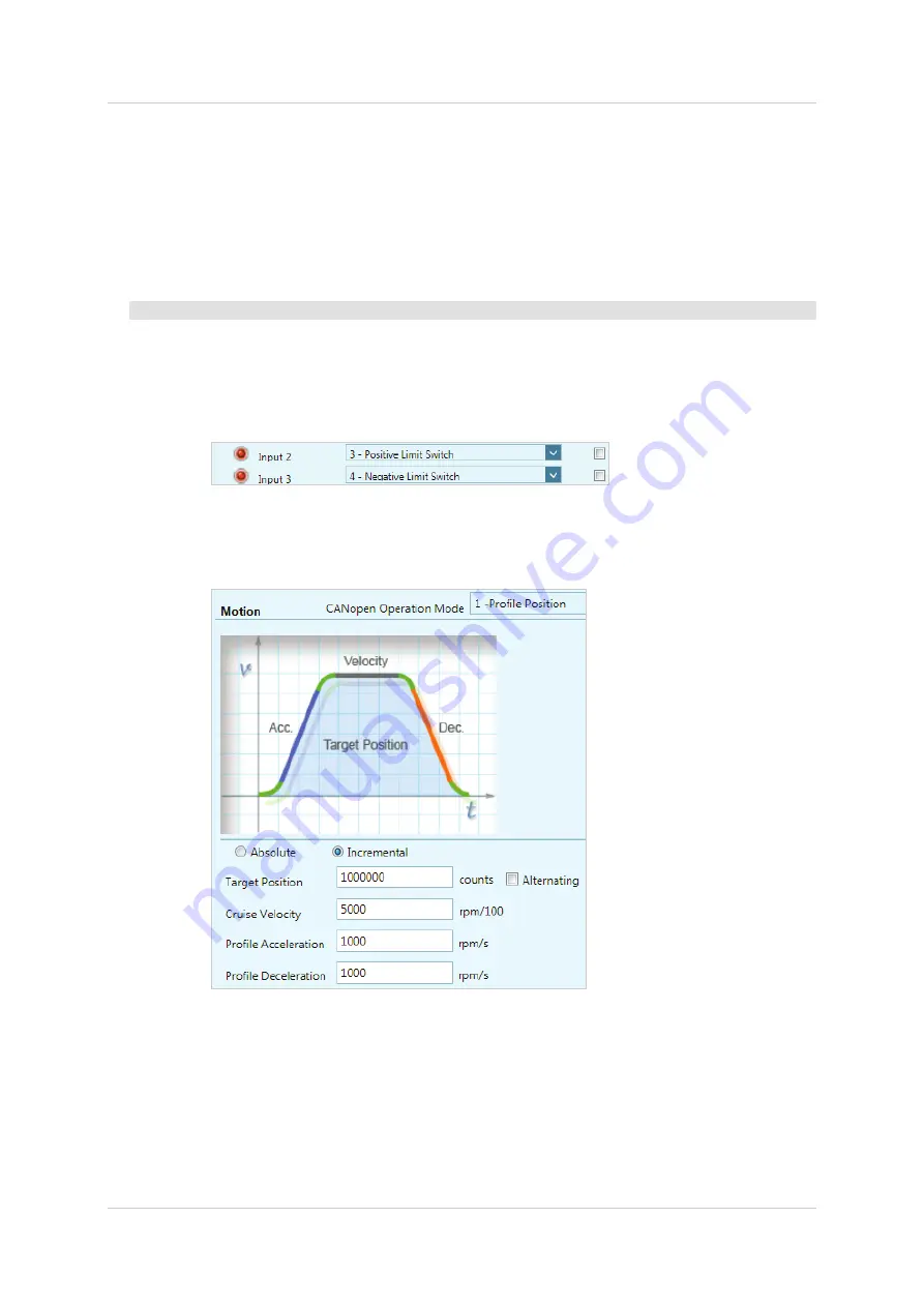
 Define a movement using the settings shown in the screen below. 


5.


Enable the drive and press 

Start

 to start the movement.  


While the motor is in motion, turn 

on

 switch 

IN 2


Observe the stopping of the motor. It stops immediately. 


Turn off switch IN 2.  Motion does not resume automatically. You must 

press 

Start

 again. 

Summary of Contents for stepIM

Page 1: ...stepIM Integrated Closed Loop Stepper Motor Technical Training Manual Manual Revision 1 0 Firmware Version 0 0 2 89 Software Version 1 41 6 0...

Page 2: ......

Page 3: ...accurate and reliable at the time of its release Servotronix Motion Control Ltd reserves the right to change the specifications of the product described in this manual without notice at any time Trad...

Page 4: ...stepIM Technical Training Manual 2...

Page 5: ...ile Position_______________________________ 18 9 Basic Operation Velocity ____________________________________ 20 10 Basic Operation Torque _____________________________________ 22 11 Velocity Control...

Page 6: ...stepIM Technical Training Manual 4...

Page 7: ...online help Alternately right click on any screen or screen element and select the Help option to access relevant information 1 2 Demo Kit Components The stepIM Demo Kit showcases the performance and...

Page 8: ...sistorSwitch Demo Kit Front Component Description stepIM x2 Motor with integrated servo drive Inertia Load Disk Aluminum disk connected to the motor shaft Digital Outputs 2 green LEDs per stepIM label...

Page 9: ...CAN In Out Interfaces D9 CAN In Out Interfaces Demo Kit Side Component Description stepIM Demo Kit Terminal Resistor Switch RJ45 CAN In Out Interfaces D9 CAN In Out Interfaces softMC 3 Ethernet Inter...

Page 10: ...Status LEDs Power Switch Powers demo kit and all components in the unit Power Connector Plug for connecting AC power to unit Demo Kit Product Label Note the location of the product label on the back o...

Page 11: ...0 terminal resistor switch on the side of the Demo Kit is set to the On position 4 Using the power cable supplied with the unit connect the Demo Kit to the power supply 5 Refer to the the diagram belo...

Page 12: ...s 7 Connect the male connector on the CAN D9 cable to the CANopen bus IN connector on the Demo Kit 8 Connect the female connector on the CAN D9 cable to the Kvaser adapter 9 Connect the Kvaser adapter...

Page 13: ...ftware ServoStudio GUI 3 From the ServoStudio navigation sidebar click Preferences Then select the Advanced tab Make sure CANopen Device is set to Kvaser Leaf 4 From the ServoStudio navigation sidebar...

Page 14: ...etected 3 You should now see that the Kvaser adapter CAN orange LED blinks indicating communication between the computer and the stepIMs is established Exercise Multiple stepIMs can be accessed throug...

Page 15: ...is displayed 2 Check the drive details for each stepIM in the Demo Kit 3 For each stepIM make a copy of the drive details If you require technical support you must provide this information to the sup...

Page 16: ...Kit Note You should not change any of the values displayed in this screen even though some of them can be manipulated Exercise Answer the following questions What is the DC voltage that is being appl...

Page 17: ...Exercise Velocity Limits What is the index of the CANopen object for Velocity Limit What is the default value of the velocity limit in hexadecimal format What is the default value in decimal format E...

Page 18: ...n is green as long as no faults exist it is red whenever a fault exists After a fault condition is removed the fault remains latched until cleared by any of the following methods Click the Faults Clea...

Page 19: ...make sure the drive is disabled 6 Right click on the red Drive Inactive segment in the status bar and then click Enable All indicators in the screen should now be green 7 Again take hold of the inert...

Page 20: ...pulses per revolution Exercise Incremental Position Command 1 Make sure drive is online and disabled 2 From the ServoStudio navigation sidebar select Motion 3 Set the Operation mode to 1 ProfilePosit...

Page 21: ...te the increase in speed 13 Reduce Cruise Velocity to 50 rpm 5000 rpm 100 Change Target Position to 40960 counts ten revolution Click Start and observe the result Count the revolutions Exercise Absolu...

Page 22: ...to 3 Profile Velocity 4 Define a velocity Jog command that will move the motor at a speed of 400 rpm for 2 seconds Enter the parameter values as shown in the screen below Profile Acceleration 10000 P...

Page 23: ...d attempt to hold it in place Observe the Demand and the Actual current values Note how the current increases in an attempt to overcome the obstacle and complete the motion 9 Changing the Jog command...

Page 24: ...Torque 4 Define a Current command of 300 mA as shown in the screen above 5 Enable the drive 6 Click the Start button to start motion 7 While the motor is turning take hold of the load disk and observ...

Page 25: ...nufacturer for the Demo Kit Do not change any of the values in this field even if they can be manipulated If you have any issues or problems make sure the values on your screen are the same as the one...

Page 26: ...nufacturer for the Demo Kit Do not change any of the values in this field even if they can be manipulated If you have any issues or problems make sure the values on your screen are the same as the one...

Page 27: ...EDs on the Demo Kit do not change except when the switch is actually toggled between on and off positions Exercise Input as Remote Enable Switch 1 Make sure the drive is disabled 2 From the ServoStudi...

Page 28: ...itch 1 Make sure switch IN 2 and switch IN 3 are off and the drive is enabled 2 In the Digital I Os screen set Input 2 Mode to Positive Limit Switch Set Input 3 to Negative Limit Switch 3 Go to the Mo...

Page 29: ...een change the Target Position to a negative value and press Start While the motor is in motion turn on switch IN 3 Observe the stopping of the motor It stops immediately Turn off switch IN 3 Motion d...

Page 30: ...om the ServoStudio navigation sidebar select Scope 3 In the Motion tab enter the following settings CANopen Operation Mode 1 Profile Position Motion Command Incremental Target Position 4096 counts Cru...

Page 31: ...nual Pre Points 10 Record variables Select the following two variables Following Error Actual Value Velocity Actual Value 6 Make sure drive is enabled then click the Move Record and Plot button in the...

Page 32: ...corded variable because its trace may be too small to view properly because the graph is scaled to the largest value of another variable For example improve the clarity of the plot by entering a scali...

Page 33: ...ich can be sent to technical support and or kept for reference It is strongly recommended that you create a report whenever you complete configuration of your application even when the system is funct...

Page 34: ...state machine It determines which commands are accepted for example motor movement cannot start unless the state machine is in the Operation Enable state The state machine also provides the ability to...

Page 35: ...e 0 X X 0 X 7 9 10 12 Quick Stop 0 X 0 1 X 7 10 11 Disable Operation 0 0 1 1 1 5 Enable Operation 0 1 1 1 1 4 16 Operation Enabled Reset Fault 1 X X X X 15 Switch On Disabled To enable the drive for o...

Page 36: ...sequence a Place the cursor in the Value field type 128 and press Enter b Place the cursor in the Value field type 6 and press Enter c Place the cursor in the Value field type 7 and press Enter d Pla...

Page 37: ...2 Switch to Profile Position operation mode opmode 1 6060h 0x1 1 3 Enable the drive 6040h 0x07 7 4 Set target position to one revolution 4096 counts 607Ah 0x1000 4096 5 Set speed to 2000 20 rpm 6081h...

Page 38: ...acceleration and sub index 4 deceleration for each object as follows Object Sub index Description Value 2F90h Sub index 2 cruise velocity 0 no velocity Sub index 3 acceleration 1000 Sub index 4 decel...

Page 39: ...rigger one predefined motion segment 0 1 2 or 3 In this exercise each of the 4 digital inputs will trigger a different motion segment meaning 4 different speeds Object Description Input Description Va...

Page 40: ...updated now appear as follows Using the Demo kit switch the inputs on off and on again Observe the response 8 Switch on input 4 Motion is fast Move input switch to off position note motion does not st...

Page 41: ...input 1 on 2F92h Motion Segment 2 0 1 0 input 2 on 2F93h Motion Segment 3 0 1 1 inputs 1 2 on 2F94h Motion Segment 4 1 0 0 input 3 on 2F95h Motion Segment 5 1 0 1 inputs 1 3 on 2F96h Motion Segment 6...

Page 42: ...te at various speeds by on different input switches Summary The binary value of three inputs defines the motion A fourth input triggers the motion Object Description Input 3 Input 2 Input 1 Velocity E...

Page 43: ...18 2 Limits Velocity Limits What is the index of the CANopen object for Velocity Limit 20EEh What is the default value of the velocity limit in hexadecimal format 0xF4240 What is the default value in...

Page 44: ...Technical Training Manual for stepIM...

Reviews: