


ENAMEL RATER MANUAL: V.10
19
4.
CONFIGURING YOUR
In order to change the configuration of the it is necessary
to remove the base panel. Instructions for doing this are given in
section 4.1 (i) and (ii). Before changing the configuration of the
it is recommended that users familiarise themselves with
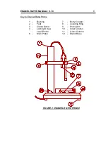
the internal layout shown in Appendix A Figure 1. A list of the
switches and jumpers of interest follows:
SWITCH/
JUMPER
NAME
LOCATION
TYPE
OPERATION
SW1
Micro board (Top
Board) To right of
SW2
Block of 8 miniature
rocker switches
numbered 1 to 8 on the
device
A switch is off when its rocker
is pressed down adjacent to
the "open" legend.
SW2
Micro board (Top
Board) To left of SW1
Block of miniature rocker
switches numbered 1 to 8
on the device
A switch is off when its rocker
is pressed down adjacent to
the "open" legend.
SW11
Applications board
(Lower Board) Below
Fuses
Block of miniature rocker
switches numbered 1 to 8
on the device
A switch is off when its rocker
is pressed down adjacent to
the "open" legend.
Mains
Selector
Switch
Applications board
(Lower Board) To the
right of the fuses
Slide Switch
Slide to correct position for
supply voltage.
J1
Micro board (Upper
Board) R.H.S.
3 position jumper
Connect the pair of pins
adjacent to the required
legend A,B or C using the
jumper.
J2
Micro board (Upper
Board)
2 position jumper
Connect the upper pair of pins
for A or the lower pair for B,
using the jumper.