Nnn-0000nn
© Copyright 2017 SecureALL Corporation
Page
6
of
18
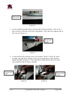
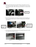
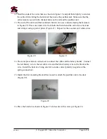
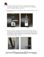
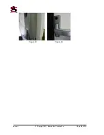
Figure 7 Figure 8
5.
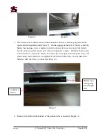
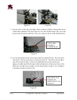
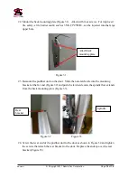
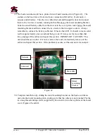
The battery box is installed next to the Lockdown Switch, with the spring toward the
open end of the pushbar unit (Figure 9). On the outside of the rail, vertically center the
battery box and use it
as a template to mark locations of two screw holes (the battery
box has 4 holes in the corners; pick 2 holes in opposite corners). Drill pilot holes using
a #40 or #38 bit. Orient the battery box inside the rail, aligned with the pilot holes, and
attach using sheet metal screws supplied in the battery holder bag. Do not install the
batteries until the wires are connected (Step 14).
Figure 9
6.
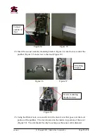
Remove the rail from the bottom of the pushbar unit as shown in Figure 10.
Lockdown
switch
Battery box
with spring
toward open
end


