Nnn-0000nn
© Copyright 2017 SecureALL Corporation
Page
15
of
18
29.
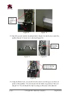
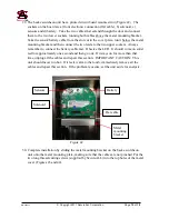
The back escutcheon unit has a printed circuit board mounted in it (Figure 42). The
sockets on the board are a) front electronic connection (flat cable), b) solenoid, c)
sensors and d) battery. Take the two cables that extend through the door and connect
them to the two lower sockets, running both cables above the metal mounting bracket.
Take the sensor/battery cable from the slot cut in the cover plate, run it below the metal
mounting bracket and then connect the two leads to the two upper sockets. Always
remember to connect the battery cable last. Observe the LED. It should come on solid
red for approximately one second and then go out. If it stays on for more than that
time, unplug all the cables and repeat this section. IMPORTANT CAUTION: This
unit should never run hot. If it feels warm to the touch, immediately remove all the
cables and repeat this section. If the problem reoccurs, set the unit aside for analysis.
Figure 42
30.
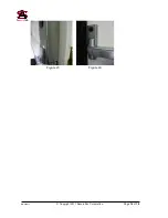
Complete installation by sliding the metal mounting bracket on the back escutcheon
unit onto the metal mounting plate, making sure that the cables are not pinched. Put the
two long thread-cutting screws (supplied by SecureALL) into the top holes of the metal
cover (Figures 43 and 44).
Flat cable
Battery
Solenoid
Sensors
Metal
mounting
bracket


