Nnn-0000nn
© Copyright 2017 SecureALL Corporation
Page
7
of
18
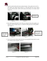
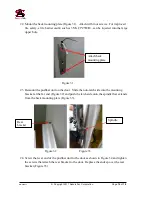
Figure 10
7.
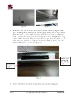
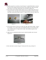
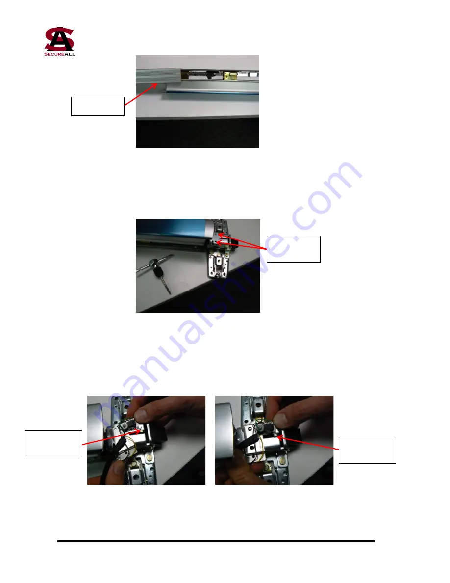
Turn the pushbar unit right side up, exposing the latching mechanism. There are two
holes at the top of the latch, right next to the pushbar. These need to be tapped using an
M5 screw tap (Figure 11).
Figure 11
8.
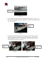
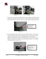
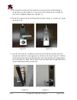
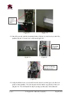
A microswitch sensor assembly needs to be installed. Figure 12 shows the sensor
assembly being placed at an angle on top of the two tapped screw holes and then
rotated into place in Figure 13. This is required to ensure the microswitch is in the
closed position when the latch is extended.
Figure 12 Figure 13
Bottom rail
Holes to be
tapped
Microswitch
closed
Microswitch
open


