950-0207revA - 17 - November 27, 2013
CONNECTION PIPING
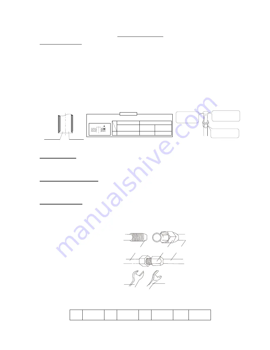
Flaring the pipe end
Cut the pipe end with a pipe cutter.
1. Remove burrs with the cut surface facing downward so that the chips do not enter the pipe.
2. Fit the flare nut on the pipe.
3. Flare the pipe.
4. Check flaring is properly done.
CAUTION!
●
Don not use mineral oil on flare part. Prevent mineral oil from getting into the system as this would
reduce the lifetime of the unit.
● Never use piping which had been used for previous installations.
● Never install a drier to this R410A unit in order to guarantee the lifetime.
● Poor flaring may cause refrigerant gas leakage.
Make sure that the
flare nut is fitted
The pipe end must
be evenly flared in
a perfect circle
Flare s inner
’
surface must
be scratch free
-
Cut exactly
at right
angles
Remove
burrs
Fl ar i ng
Set exactly at the position shown below
A
Die
A
0-0.002"
0.003-0.005" 0.005-0.007"
Flare tool for R410A
Clutch-type
Clutch-type
(Rigid-type)
Wing-nut type
(lmperial-type)
Conventional flare tool
Identify Line Sets
Mark the line sets as necessary to prevent crossed connections. Crossed line sets will prevent proper
operation.
Identify Interconnect cables
Connect interconnect cable and identify cable at both ends. Cable routed to terminal from rear of
indoor unit.
Connecting Line Set
1. Use torque wrenches when tightening the flare nuts to prevent damage to the flare nuts and gas
leaks.
2. Let the flare end of the copper pipe point at the screw and then tighten the screw by hand.
3. After that, tighten the screw by the torque wrench until it clatters. See Fig. 17 below.
Pipe
Pipe
Flare Nut
Spanner
Torque Wrench
4. Refer the Table 6 below to tighten the nuts.
Table 6: Tightening Torque
1/4
”
11
– 22
lbs ft.
3/8
”
23
– 29
Lbs ft.
1/2
”
33
– 37
lbs ft.
5/8
”
44
– 48
Lbs ft.
Note
:
Exceeding the tightening torque will damage the flare surface.
Figure 18
.
Figure 17
.


