Schulze BS-350 LST Original Operating Manual Download Page 47


Operation 

Filling the cooling water 

8.3 


Table saw BS-350 LST, BS-400 LST-E230, BS-400 LST-E400, BS-500 LST 

47

/80 

8.3 

Filling the cooling water 


Attention 

  If the cutting blade is not adequately supplied with cooling water during 

wet cutting, overheating may occur, leading to premature wear, failure or 
segment loss of the cutting blade. 

  The outlet nozzle of the water hose on the blade guard must not be 

blocked. 

  The water pump must not run dry. 

  Check the level in the cooling water tank regularly and top up if neces-

sary. 

  If there is a risk of frost, drain the cooling water tub and open the shut-

off valve. 


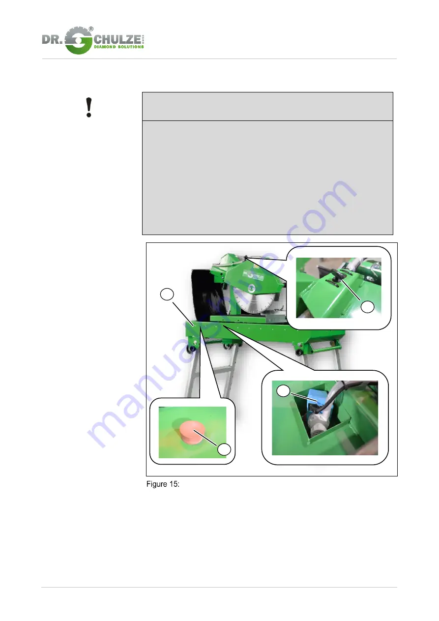
  Water coolant tank with water pump 


1. 

Ensure that the rubber stopper (4) is inserted in the tank’s water outlet. 

2. 

Fill enough water into the water coolant tank (1) that that pump (2) can 
always run. 

3. 

Check that the shut-off valve is set correctly for each cut: 


Wet cutting: Shut-off valve opened. 


Dry cutting: Shut-off valve closed. 


Summary of Contents for BS-350 LST

Page 1: ...Translation Table saw BS 350 LST BS 400 LST E230 BS 400 LST E400 BS 500 LST Device Name Table saw BS 350 LST BS 400 LST E230 BS 400 LST E400 BS 500 LST Device Number Nameplate Year of Manufacture 2018...

Page 2: ...personnel 11 Qualified electricians 11 Unauthorized persons 11 3 Safety 12 3 1 General 12 3 2 Intended use 12 3 3 Non intended use 12 3 4 Responsibility of the operator 13 Operator 13 Responsibilitie...

Page 3: ...cription 30 5 3 Operating and display elements 32 6 Transport and storage 34 6 1 Delivery 34 6 2 Transport 34 Transport inspection 34 Transport symbols 35 6 3 Transport in plant 36 6 4 Storage 38 Stor...

Page 4: ...tank 61 Clean the water fork 63 Replacing the V belt 64 9 3 Cleaning 66 Cleaning the machine 66 10 Faults 67 10 1 Actions in case of faults 67 10 2 Process related faults 68 11 Removal and disposal 69...

Page 5: ...t for safe operation of the machine is the adherence to all of the safety and operation instructions provided Personnel must therefore have carefully read this operating manual before beginning any wo...

Page 6: ...with the operating manual the following please note the following explanations of the typographical conventions Numbering Bullet points of the first level Bullet points of the second level Handling i...

Page 7: ...to death or serious injuries if it is not avoided Warning indicates a possible hazardous situation which can lead to death or serious injuries if it is not avoided Caution indicates a possible hazard...

Page 8: ...contact persons for your region by telephone and at any time by fax e mail or via the Internet In addition our personnel are always interested in any of your experiences and new information arising f...

Page 9: ...ry conditions of the manufacturer and the legal regulations valid at the time of the conclusion of the contract apply The manufacturer assumes no liability for damage due to Failure to comply with thi...

Page 10: ...achine Dr Schulze GmbH reserves all rights for the licensing of use for publication or distribution of copies or information from this operating manual to third parties In case of infringement the man...

Page 11: ...o on the basis of the occupational training knowledge and experience of the relevant regulations are in a posi tion to carry out the work assigned to them properly recognize possible dangers independe...

Page 12: ...ral sandstone washed concrete concrete blocks and aerat ed concrete It is designed for continuous use on building sites or in factories and may only be used for industrial purposes and only operated b...

Page 13: ...workplace lighting is in accordance with national and local regulations determine by means of a risk assessment any possible additional haz ards which result from the special conditions of use at the...

Page 14: ...nd cleaning of the machine properly must have fully read and understood the operating manual before the commencement of work the prescribed personal protective equipment applies It must be checked reg...

Page 15: ...welry For long hair wear a hairnet Use of special cut resistant work gloves to protect the hands against abrasion grazes scratches scrapes puncture wounds piercing or similar injuries to the surface o...

Page 16: ...tes hazards from hot surfaces Where safety notices are not observed there is a danger of burns and serious skin injuries due to heat indicates hazards due to catching Failure to observe the safety ins...

Page 17: ...rmal oper ation excludes inspection maintenance cleaning and repair The work zone green area may only be entered by authorized operational personnel to operate the machine Danger Zone The person in wh...

Page 18: ...ne make sure that nobody can be endan gered by the starting machine Nobody is allowed to access the running ma chine Do not bring body parts into the area of moving parts when operating the machine Al...

Page 19: ...which are designed for use in the respective environment and whose core cross section is sufficiently dimen sioned Completely unroll a cable reel to prevent overheating Protect the cable against heat...

Page 20: ...ed Emergency stop button The emergency stop button 1 is a push button It is used to shut off the power supply and is depressed both for turning off and in case of danger After pressing the emergency s...

Page 21: ...BS 400 LST E230 BS 400 LST E400 BS 500 LST 21 80 Blade guard The machine may only be operated with the blade guard closed 1 This provides work safety Position of the blade guard on the Table saw BS 3...

Page 22: ...on Red button 0 switch machine off Position of the control box on the Table saw BS 350 LST BS 400 LST E230 BS 400 LST E400 BS 500 LST A bimetallic overload protector protects the drive and prevent th...

Page 23: ...dent the following rules of conduct should be ob served Immediately trigger emergency stop Take first aid measures Remove affected persons from the danger zone Inform those in charge at the site Call...

Page 24: ...400 LST E400 BS 500 LST Machine System Information Value unit Drive motor power BS 350 LST BS 400 LST E230 BS 400 LST E400 BS 500 LST 2 2 kW 2 2 kW 3 0 kW 3 0 kW Voltage BS 350 LST BS 400 LST E230 BS...

Page 25: ...0 LST E400 BS 500 LST 650 mm 650 mm 650 mm 650 mm Max cutting depth BS 350 LST BS 400 LST E230 BS 400 LST E400 BS 500 LST 120 mm 170 mm 170 mm 220 mm Dimension BS 350 LST BS 400 LST E230 BS 400 LST E4...

Page 26: ...T E400 BS 500 LST Machine System Information Value unit Weight approx BS 350 LST BS 400 LST E230 BS 400 LST E400 BS 500 LST 70 kg 116 kg 116 kg 119 kg Protection class IP 55 Sound pressure level measu...

Page 27: ...aw BS 350 LST BS 400 LST E230 BS 400 LST E400 BS 500 LST 27 80 4 3 Name plate The rating plate is used to identify the component assembly The specifica tion of the type plate facilitates communication...

Page 28: ...BS 500 LST is designed so that the water cooling and splitting mechanism are fixed on the basic frame The cutting table can be moved between its limit stops Table saw BS 350 LST BS 400 LST E230 BS 40...

Page 29: ...saw BS 350 LST BS 400 LST E230 BS 400 LST E400 BS 500 LST 29 80 3 Shut off valve cooling water 9 Water container 4 Spray guard 10 Guide carriage 5 Cutting blade 11 Cutting head 6 Cutting table 12 Driv...

Page 30: ...r tank directly to the cutting blade This increases the service life of the cutting blade and serves to bind dust The shut off valve on the blade guard closes the water supply during dry cutting The c...

Page 31: ...Construction and function 5 Functional description 5 2 Table saw BS 350 LST BS 400 LST E230 BS 400 LST E400 BS 500 LST 31 80 BS 350 LST Cutting head adjustment 5 6...

Page 32: ...nts 32 80 Table saw BS 350 LST BS 400 LST E230 BS 400 LST E400 BS 500 LST 5 3 Operating and display elements Switchbox Controls on the switchbox 1 Main switch with emergency off function 2 On button g...

Page 33: ...Table saw BS 350 LST BS 400 LST E230 BS 400 LST E400 BS 500 LST Operating elements of the Table saw BS 350 LST BS 400 LST E230 BS 400 LST E400 BS 500 LST 1 Shut off valve of the cooling water supply t...

Page 34: ...packaging Only transport the machine with the transport lock installed Always remove the transport lock during assembly The transport product is packaged securely and environmentally for the ex pecte...

Page 35: ...damage on the transport documents and mention it on the delivery note of the transporter Transport symbols There are symbols on the transport product that correspond to the contents which must be obse...

Page 36: ...h the machine only two people are needed To transport it further it is recommended to use suitable means of transporta tion Transport wheels 1 Secure the table against rolling away using the locking s...

Page 37: ...ge 6 Transport in plant 6 3 Table saw BS 350 LST BS 400 LST E230 BS 400 LST E400 BS 500 LST 37 80 4 Fold away the wheels 1 of the adjustable feet by lifting the rear area of the machine and folding th...

Page 38: ...s Prior to storage the machine must be properly cleaned lubricated and dried in accordance with the instructions in the maintenance section in order to protect it from corrosion Storage conditions Onl...

Page 39: ...following when handling the packaging material Always dispose of packing in an environmentally responsible manner Observe local regional applicable statutory regulations Where necessary use a qualifi...

Page 40: ...fold them out Insert each of them in their designed seating slot at the corners of the frame until it stops and then tighten the thumb screws 2 Take care that the machine stands on solid ground when c...

Page 41: ...al connection of the machine may only be made via a suitable power distribution board Portable machines used outdoors must be con nected through a fault current circuit breaker The Table saw BS 350 LS...

Page 42: ...ed protective devices oth erwise there is a risk of injury Ensure before all work that the safety systems are correctly installed and function without error Never disable safety equipment Responsibili...

Page 43: ...d by the manufacturer and labelled as such may be used for dry cutting Acute risk of injury arises from the use of unsuitable cutting discs Attention The bore diameter of the cutting blade must match...

Page 44: ...nut 3 using the tools supplied ring spanner 4 and Allen key 5 and then unscrew it To release it hold the cutting shaft fast with the second tool supplied ring spanner 4 4 Remove the outer driver flang...

Page 45: ...must always be appropriate for the material to be cut Always work in the specified performance range 8 Put on the outer driver flange 6 9 First attach the nut 3 and then do it up using the tools suppl...

Page 46: ...8 Operation 8 2 Clamping changing the cutting blade 46 80 Table saw BS 350 LST BS 400 LST E230 BS 400 LST E400 BS 500 LST Mounting the blade guard 10 Close the blade guard 2 with the latches 1 1 2...

Page 47: ...se on the blade guard must not be blocked The water pump must not run dry Check the level in the cooling water tank regularly and top up if neces sary If there is a risk of frost drain the cooling wat...

Page 48: ...g water 48 80 Table saw BS 350 LST BS 400 LST E230 BS 400 LST E400 BS 500 LST Note When wet cutting the rotating cutting blade must be sprayed with suffi cient cooling water You can regulate the amoun...

Page 49: ...the blade guard is closed 3 Check the level of cooling water and the position of the shut off valve 4 Connect the power at the mains plug 1 Turn on the Table saw BS 350 LST BS 400 LST E230 BS 400 LST...

Page 50: ...E400 BS 500 LST If the cutting disc is turning in the wrong direction press the emergency off button 4 Disconnect the Table saw BS 350 LST BS 400 LST E230 BS 400 LST E400 BS 500 LST from the mains con...

Page 51: ...er of injury due to rotating cutting blade During operation do not reach into the danger zone of the machine In addition the machine may only be operated with mounted protective de vices Ensure before...

Page 52: ...BS 400 LST E230 BS 400 LST E400 BS 500 LST on 4 Switch on workpiece cooling 5 Move the cutting table with the workpiece by pushing the manual guide 1 towards the cutting disc 6 Continue to push the c...

Page 53: ...0 LST BS 400 LST E230 BS 400 LST E400 BS 500 LST 53 80 8 6 Switch Off Pause 1 After the mobile sections has reached the rear stop press the emergency stop button 1 Turn off the Table saw BS 350 LST BS...

Page 54: ...tension the V belt when the machine is shut down for longer periods BS 400 LST E400 BS 500 LST see section changing V belt Turn off the Table saw BS 350 LST BS 400 LST E230 BS 400 LST E400 BS 500 LST...

Page 55: ...on 7 Inform those in charge at the site 8 If required alert a doctor and the fire service 9 Retrieve injured persons and apply first aid 10 Disconnect the plug 11 Keep the approaches for rescue vehicl...

Page 56: ...ver 2 and the locking mecha nism 3 This allows the cutting disc to be positioned for full or reduced cut depths In this way an even depth of cut can be guaranteed along the entire length Setting the c...

Page 57: ...blade protector fixtures and remove the blade protector Place a steel right angle 2 against the limit stop 3 of the cutting table Abbildung 21 Adjust cutting table Release the 4 screws of the cutting...

Page 58: ...er of injury due to electrical voltage There is a risk of injury when touching live parts All electrical connection work may only be performed and inspected and approved by trained electricians Before...

Page 59: ...lade for wear If worn or damaged replace the cutting blade Always clamp a cutting blade that fits the workpiece After every use completely clean the water pump Use a suction strainer and rinse through...

Page 60: ...e annually before first use Have the machine checked for electrical safety in accordance with VBG4 Accident prevention regula tions 5 By qualified electricians The test must be documented See manufact...

Page 61: ...is in a sludge protection nest 2 in the water coolant tank 3 The sludge protection nest in the water coolant tank ensures that the sludge does not deposit on the water pump and thus only relatively c...

Page 62: ...ble saw BS 350 LST BS 400 LST E230 BS 400 LST E400 BS 500 LST 4 If the machine is shut down for a long time dismount the water pump 3 and clean it according to manufacturer instructions 5 Insert the d...

Page 63: ...ter fork Clean the water fork 1 Open the blade protector by loosening the screws and removing the blade protector 2 Dismount the cutting disc see section 8 2 3 Blast out the water fork with pressurise...

Page 64: ...Table saw BS 350 LST BS 400 LST E230 BS 400 LST E400 BS 500 LST Replacing the V belt No V belt is pre attached to the Table saw BS 350 LST direct drive Procedure to change the V belt BS 400 LST E400...

Page 65: ...ing the blade protector 2 Dismount the cutting disc see section 8 2 3 Dismount the coolant tube 4 Dismount the V belt covers upper and lower 5 Release the drive motor s attachment screws and loosen th...

Page 66: ...lations for environmental protection and disposal must be ob served Wear appropriate personal protective equipment No cleaning materials containing solvents may be used Observe the instructions in the...

Page 67: ...er the emergency stop button 2 Switch off all power supplies and secure them against being turned back on 3 Inform those in charge at the site 4 Depending on the type of fault report the fault to the...

Page 68: ...o tor Drive shuts off during the cutting pro cess The machine can be switched on again after a break The feed during the cutting process is too large The cut takes place The cutting blade is worn dull...

Page 69: ...pplier use personal body protection equipment 11 2 Disposal This machine complies with Directive 2012 19 EU WEEE of 08 13 2012 The manufacturer undertakes to take back the associated equipment for dis...

Page 70: ...adjustment 31 Controls on the switchbox 32 Operating elements of the Table saw BS 350 LST BS 400 LST E230 BS 400 LST E400 BS 500 LST 33 Transport wheels 36 Open blade guard 43 Mounting the cutting bl...

Page 71: ...400 BS 500 LST 71 80 12 2 List of tables Table 1 Version status 5 Table 2 Environmental conditions 24 Table 3 Technical data of the Table saw BS 350 LST BS 400 LST E230 BS 400 LST E400 BS 500 LST 24 T...

Page 72: ...13 Annex 12 2 List of tables 72 80 Table saw BS 350 LST BS 400 LST E230 BS 400 LST E400 BS 500 LST 13 Annex Appendix 1 Conformity Statement Appendix 2 Circuit diagram Appendix 3 Replacement parts list...

Page 73: ...in the meaning of the Machinery Directive 2006 42 EC Annex II 1A 13 1 Table saw BS 350 LST BS 400 LST E230 BS 400 LST E400 BS 500 LST 73 80 13 1 Declaration of conformity within the meaning of the Mac...

Page 74: ...ble saw BS 350 LST BS 400 LST E230 BS 400 LST E400 BS 500 LST 74 80 Table saw BS 350 LST BS 400 LST E230 BS 400 LST E400 BS 500 LST 13 2 Circuit diagram for the Table saw BS 350 LST BS 400 LST E230 BS...

Page 75: ...Annex 13 Replacement parts list 13 3 Table saw BS 350 LST BS 400 LST E230 BS 400 LST E400 BS 500 LST 75 80 13 3 Replacement parts list Replacement parts list...

Page 76: ...13 Annex 13 3 Replacement parts list 76 80 Table saw BS 350 LST BS 400 LST E230 BS 400 LST E400 BS 500 LST Replacement parts list...

Page 77: ...Annex 13 Replacement parts list 13 3 Table saw BS 350 LST BS 400 LST E230 BS 400 LST E400 BS 500 LST 77 80 Replacement parts list...

Page 78: ...13 Annex 13 3 Replacement parts list 78 80 Table saw BS 350 LST BS 400 LST E230 BS 400 LST E400 BS 500 LST Replacement parts list...

Page 79: ...0 M8 N 17 1 Head 18 1 Head mount 19 1 Motor 20 1 Disc 21 1 Motor flange 22 1 Bolt 23 2 Washer DIN 471 12 x 1 24 1 Lever 25 1 Disc 26 1 Gas pressure support 27 1 Cap 28 2 Protective mat 29 1 Rivets 30...

Page 80: ...saw BS 350 LST BS 400 LST E230 BS 400 LST E400 BS 500 LST 57 1 Water pump 58 2 Screw ISO 4017 M8 x 16 N 59 1 Hose valve 60 1 Hexagon Nut ISO 4032 M6 W N 61 4 Wheel 62 4 Cap 63 1 Linch pin 64 2 Strap...

Reviews: