78
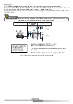
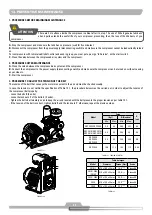
Compressor command at full load
1.
When the pressure goes up reaching the value set on the pressure switch
P1
, it will deenergize the solenoid valve
VS1
closing the com-
mand way that kept the admission valve totally open.
Compressor control in relief
1.
If consumption is lower than the production of the compressor, the pressure of the system will increase until the value set on the pres-
sure switch
P1
, when solenoid valve
VS1
will deenergize and close, which in turn will close the admission valve, allowing the release of
compressed air.
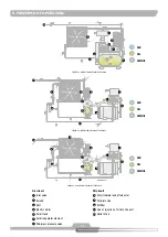
2.
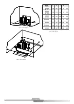
With the admission valve closed, the depressurization of the tank
3
will begin until the volume aspired by the by-pass holes is equal to
the volume released by the relief, equalizing the pressure of the tank between 3.1 to 4.1 barg (45 to 60 psig) required in order to guarantee
the lubrication of the system, reducing the power around 60% while in this regime.
3.
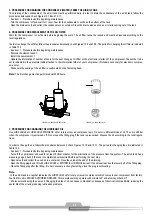
If a pressure drop occurs due to an increase in consumption, the solenoid valve
VS1
will be deenergized by the pressure switch
P1,
returning the compressor to full load operation.
Command Mode
The compressor operates in continuous mode and goes into relief at maximum operating pressure and only turns off if there is no air con-
sumption that causes a pressure drop in the system of 1.03 to 1.4 (15 to 20 psig) during the time set in the timer of the electric panel. This
relief time can be set for a period of 5 to 30 minutes.
Note:
It is not convenient that the motor start more than 10 (ten) times an hour.
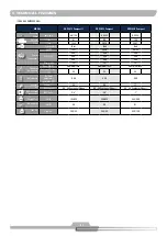
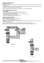
10. COMMAND SYSTEM
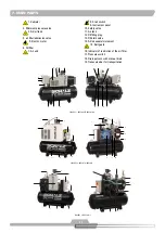
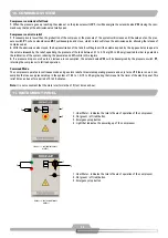
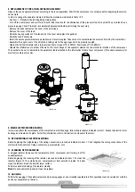
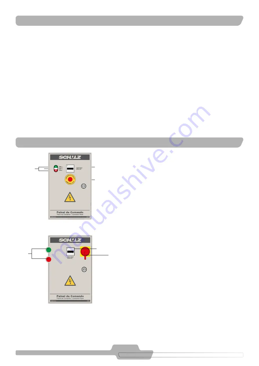
11. INSTRUMENT PANEL
1. Hour Meter - indicates the total of hours of operation of the compressor
2. On (green) / off (red) button
3. Emergency stop button
FIGURE 11.2 - INSTRUMENT PAINEL
MODEL II
0 0 0 0 0 0 0
h
1 100
0 0 0 0 0 0 0
h
1 100
1
2
3
1. Hour Meter - indicates the total of hours of operation of the compressor
2. On (green) / off (red) button
3. Emergency stop button
4. Light that indicates the powering up of the compressor
1
2
3
4
0 0 0 0 0 0 0
h
1 100
0 0 0 0 0 0 0
h
1 100
FIGURE 11.1 - INSTRUMENT PAINEL
MODEL I


