Installation
EN
· 30.30.01.02851 · 01 · 03/22
69 / 96
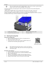
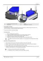
1
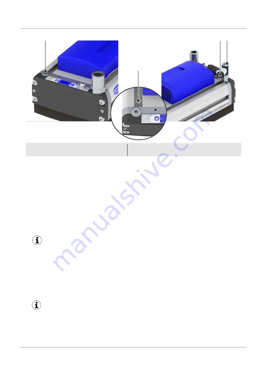
Connection for separation function
2
Marking
3
Valve screw
4
Compressed air connection
Compressed air connection
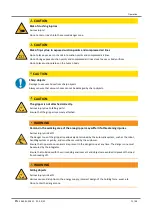
The compressed air is controlled using connection (4). The compressed air is switched using a 3/2-way valve. This
valve is not included in the equipment delivered with the gripper.
The separation function is started up as follows:
Start of operations
1.
Remove the plug on the connection (1)
2.
Connect the supplied throttle return valve to the connection using an extension.
3.
Tighten valve screw (1) using a flathead screwdriver (clockwise direction).
4.
Apply the compressed air using connection (2) (8/6 hose).
5.
Slowly loosen valve screw (1) until you have achieved the necessary separation effect.
This setting cannot be made at the factory because it must be adapted to the individual materials being
lifted.
Description of the Separation Function
1.
Place the gripper on the product. Sealing plates should be compressed by at least 40%.
2.
Switch on the suction pulse. After an evacuation time of approx. 0.5 to 1.0 seconds, lift a few millimeters.
3.
Start the separation pulse. Continue lifting during the separation period.
4.
Switch off the separation pulse just after the 2nd layer is separated. The separation pulse can only run for a very
brief period; otherwise there is a risk of destroying the sealing plate.
If necessary, you can also use two valve screws per gripper.
The separation function is available for the valve technology SVK and SW.
1
4
3
2

