


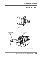

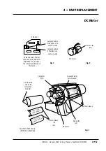


4 • PART REPLACEMENT
DC Motor
Edition 1
•
January 1996 Service Manual • ScanMate 4000/5000
4•15c
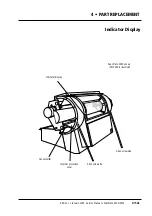
DC motor
Allen screws
B
(x2)
Inner cover
(earlier models)
Inner cover
(later models)
Connector
PCB
Screws
D
(x2)
Access hole for
set screws
C
2.5 mm allen
screws
A
(only later
models)
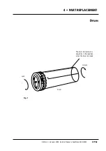
Drum sleeve
DC motor
Screws
E
(x3)
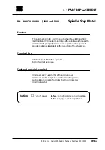
Jumper position
if the green con-
nector is used
There are two different
types of board, (PCB011D
and PCB 011F), however
the jumper positioning is
the same
Jumper position
if the black con-
nector is used
PCB 011F
Green
Black
Fig. 1
Fig. 2
Fig. 3
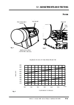
ScanMate 5000 shown
(SM 4000 is identical)
Summary of Contents for ScanMate 4000
Page 1: ...ScanMate 5000 ScanMate 4000 ...
Page 6: ......
Page 16: ......
Page 18: ......
Page 20: ......
Page 22: ......
Page 24: ......
Page 28: ......
Page 40: ......
Page 44: ......
Page 48: ......
Page 52: ......
Page 56: ......
Page 60: ......
Page 64: ......
Page 68: ......
Page 72: ......
Page 76: ......
Page 80: ......
Page 84: ......
Page 88: ......
Page 92: ......
Page 96: ......
Page 100: ......
Page 102: ......
Page 106: ......
Page 110: ......
Page 114: ......
Page 118: ......
Page 122: ......
Page 126: ......
Page 130: ......
Page 134: ......
Page 138: ......
Page 142: ......
Page 146: ......
Page 150: ......
Page 154: ......
Page 156: ......
Page 162: ......
Page 164: ......
Page 170: ......
Page 171: ...ScanMate 4000 Type 250 Circuit Connection Diagram ...
Page 172: ...ScanMate 5000 Type 210 Circuit Connection Diagram ...
Page 174: ......