


How to test
1
• Fit a terminator to a SCSI connector on the scanner and SCSI cable
and RS 232 service cable to the scanner and PC.
2
• Switch on the scanner in the SCSI mode.
3
• Start up Photoshop plug-in.
4
• Mount a piece of aluminium foil onto the drum.
5
• Select the following settings in Photoshop:
Transmission color
Gamma 1.4
Neutral gradation curve
1200 dpi resolution
White/black point:
max. 255
min. 0
6
• Scan an area of approximately 20 x 20 mm in the middle of the
aluminium foil, without making a preview first.
7
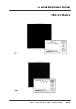
• Select
adjust level
and move the left hand (black) marker to the
right until level 2 is obtained (fig. 1).
8
• Now move the right hand (white) marker to the left until level 4 is
obtained.
9
• Check the image and ensure that there are no stripes on the screen,
(fig. 1).
10
• Fig. 2 shows an example of stripes in shadow when the black
marker level is between 0 and 1. If there are stripes on the screen
after steps 9 and 10, contact ScanView´s support department.
Service Manual • ScanMate 4000/5000 Edition 1
•
January 1996
Stripes in Shadow
5•13b
Summary of Contents for ScanMate 4000
Page 1: ...ScanMate 5000 ScanMate 4000 ...
Page 6: ......
Page 16: ......
Page 18: ......
Page 20: ......
Page 22: ......
Page 24: ......
Page 28: ......
Page 40: ......
Page 44: ......
Page 48: ......
Page 52: ......
Page 56: ......
Page 60: ......
Page 64: ......
Page 68: ......
Page 72: ......
Page 76: ......
Page 80: ......
Page 84: ......
Page 88: ......
Page 92: ......
Page 96: ......
Page 100: ......
Page 102: ......
Page 106: ......
Page 110: ......
Page 114: ......
Page 118: ......
Page 122: ......
Page 126: ......
Page 130: ......
Page 134: ......
Page 138: ......
Page 142: ......
Page 146: ......
Page 150: ......
Page 154: ......
Page 156: ......
Page 162: ......
Page 164: ......
Page 170: ......
Page 171: ...ScanMate 4000 Type 250 Circuit Connection Diagram ...
Page 172: ...ScanMate 5000 Type 210 Circuit Connection Diagram ...
Page 174: ......