


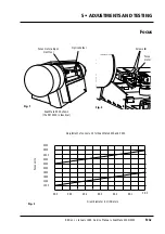


Function
Light tube adjustment sets the mechanical alignment of the optical
system (light source and sensor).
Technical data
TP46
- test point
TP100
- ground
Tools and equipment required
C-spanner for light unit lock ring
2 mm allen key for lamp cover and back cover mounting screws
2.5 mm allen key for focus motor mounting screws
3 mm allen key (T-handle) for right hand drum cover mounting screws
Extension board (part of the service kit)
Voltmeter with probes
5 • ADJUSTMENTS AND TESTING
Light Tube
Edition 1
•
January 1996 Service Manual • ScanMate 4000/5000
5•2a
Caution!
☛
Turn off power
• Before
connecting or disconnecting cables.
• Before
carrying out service operations.
☛
When the hardware drawer is partially removed and power turned
on, ensure that the open side of the heat sink on the driver board
is covered, with, for example a piece of cardboard or paper, in
order that cooling is still effective.
Summary of Contents for ScanMate 4000
Page 1: ...ScanMate 5000 ScanMate 4000 ...
Page 6: ......
Page 16: ......
Page 18: ......
Page 20: ......
Page 22: ......
Page 24: ......
Page 28: ......
Page 40: ......
Page 44: ......
Page 48: ......
Page 52: ......
Page 56: ......
Page 60: ......
Page 64: ......
Page 68: ......
Page 72: ......
Page 76: ......
Page 80: ......
Page 84: ......
Page 88: ......
Page 92: ......
Page 96: ......
Page 100: ......
Page 102: ......
Page 106: ......
Page 110: ......
Page 114: ......
Page 118: ......
Page 122: ......
Page 126: ......
Page 130: ......
Page 134: ......
Page 138: ......
Page 142: ......
Page 146: ......
Page 150: ......
Page 154: ......
Page 156: ......
Page 162: ......
Page 164: ......
Page 170: ......
Page 171: ...ScanMate 4000 Type 250 Circuit Connection Diagram ...
Page 172: ...ScanMate 5000 Type 210 Circuit Connection Diagram ...
Page 174: ......


