


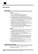


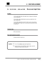


Function
The driver board differs between the ScanMate 4000 and 5000, (both
0200 and 0210 models), but removal and assembly is identical.
It contains the power supply to all analog and digital circuits and cont-
ains the motor driver and lamp driver circuits.
Technical data
+/- 5 VDC analog, + 12 VDC analog
+/- 15 VDC analog, + 19 VDC analog
+/- 20VDC analog, + 5 VDC digital
Tools and materials required
2 mm allen key for back cover and hardware unit mounting screws
Posidrive screwdriver
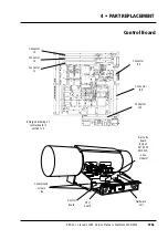
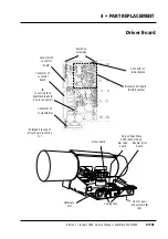
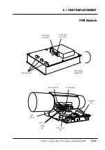
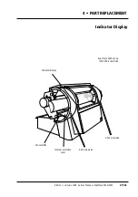
4 • PART REPLACEMENT
PN
960 21 000 40
(4000)
Driver Board
PN
960 20 000 40
(5000 - 0200 model)
PN
960 21 000 40
(5000 - 0210 model)
Edition 1
•
January 1996 Service Manual • ScanMate 4000/5000
4•10a
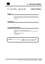
Caution!
☛
Turn off power
• Before
connecting or disconnecting cables.
• Before
carrying out service operations.
☛
Wait at least 2-3 minutes after power is turned off before rem-
oving the driver board, in order for the capacitors to drain.
Summary of Contents for ScanMate 4000
Page 1: ...ScanMate 5000 ScanMate 4000 ...
Page 6: ......
Page 16: ......
Page 18: ......
Page 20: ......
Page 22: ......
Page 24: ......
Page 28: ......
Page 40: ......
Page 44: ......
Page 48: ......
Page 52: ......
Page 56: ......
Page 60: ......
Page 64: ......
Page 68: ......
Page 72: ......
Page 76: ......
Page 80: ......
Page 84: ......
Page 88: ......
Page 92: ......
Page 96: ......
Page 100: ......
Page 102: ......
Page 106: ......
Page 110: ......
Page 114: ......
Page 118: ......
Page 122: ......
Page 126: ......
Page 130: ......
Page 134: ......
Page 138: ......
Page 142: ......
Page 146: ......
Page 150: ......
Page 154: ......
Page 156: ......
Page 162: ......
Page 164: ......
Page 170: ......
Page 171: ...ScanMate 4000 Type 250 Circuit Connection Diagram ...
Page 172: ...ScanMate 5000 Type 210 Circuit Connection Diagram ...
Page 174: ......