background image

4 INT-KWRL 

SATEL 


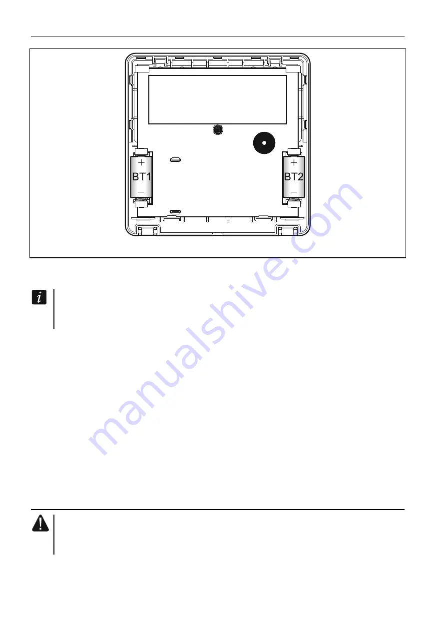
Fig. 3. Keypad enclosure inside with batteries installed. 

 
3.  Put the cover on the catches and snap the enclosure shut. 
4.  Place the keypad in the location intended for its installation. 

If you want to hold the keypad in your hand when checking the radio signal level, grab 
the device from its left side (on its right side, there is the antenna, which must not be 
covered). 

5.  Check the level of signal received from the keypad by the ACU-120 / ACU-270 controller. 

If the signal level is lower than 40%, select another place for installation. Sometimes, it is 
sufficient to shift the device ten or twenty centimeters to obtain a considerable 
improvement in the signal quality. Only after the optimal level of radio signal is achieved 
can you proceed to the next step. 

6.  Open the keypad enclosure (Fig. 2). 
7.  Place the enclosure base against the wall and mark location of the mounting holes. 
8.  Drill the holes in the wall for wall plugs (screw anchors). 
9.  Using wall plugs (screw anchors) and screws, secure the enclosure base to the wall. 

Select wall plugs and screws specifically intended for the mounting surface (different for 
concrete or brick wall, different for plaster wall, etc.). When installed, the device must 
withstand a pull-off force of at least 50 N. 

10. Put the cover on the catches and snap the enclosure shut. 
11. Lock the cover using screw. 

3.1  Adding the keypad to the wireless system 

Before adding a keypad, make sure that the controller terminals CKM and DTM 
are connected with the keypad bus of the control panel, and the switch 8 in the 
controller is set to the OFF position. 

You can add the wireless keypad to the ABAX system by using either a computer with 
DLOADX program installed, or an LCD keypad. The controller allows for registering of up to 4 
INT-KWRL keypads. If no wired keypad is connected to the control panel, you can only add 
the first wireless keypad using the DLOADX program (to establish communication between 

Summary of Contents for INT-KWRL

Page 1: ...int kwrl_en 05 18 Wireless keypad INT KWRL Firmware version 2 15 SATEL sp z o o ul Budowlanych 66 80 298 Gda sk POLAND tel 48 58 320 94 00 www satel eu...

Page 2: ...nually upgrade the quality of its products which may result in some changes of their technical specifications and firmware The current information on the introduced modifications is available on our w...

Page 3: ...5 03 or newer connected to the INTEGRA INTEGRA Plus control panel The ACU 120 ACU 270 controller which is to support the INT KWRL keypad must be connected to the expander bus controller terminals CKE...

Page 4: ...e mode is entered after 20 seconds since the last key press after preset time if the active mode was started automatically see description of the WAKE UP parameter section Settings stored in ABAX syst...

Page 5: ...ect installation of the battery The used batteries must not be discarded but should be disposed of in accordance with the existing rules for environment protection The keypad is designed for indoor in...

Page 6: ...of the mounting holes 8 Drill the holes in the wall for wall plugs screw anchors 9 Using wall plugs screw anchors and screws secure the enclosure base to the wall Select wall plugs and screws specifi...

Page 7: ...cel adding the keypad click on the Quit button 9 The New device window will close 10 The new keypad will appear in the table in INT KWRL tab 11 Click on the Keypads identification button the new keypa...

Page 8: ...roller name INT KWRL tab see Fig 4 LCD keypad SERVICE MODE STRUCTURE HARDWARE EXPANDERS SETTINGS controller name SETTINGS wireless keypad name 4 1 1 Description of parameters and options Given in the...

Page 9: ...cription of parameters and options Given in the square brackets are the names of parameters and options presented on the keypad display Keypad Name individual name of the keypad up to 16 characters Pa...

Page 10: ...keypad can inform on fire alarms in selected partitions CHIME signal of zones Chime zones zones the violation of which is audibly signaled by the keypad If the zone is armed violation will not trigger...

Page 11: ...ime format the way how date and time will be presented on the display LCD backlight the way how the display backlight will work in the active mode not present disabled permanent 50 enabled brightness...

Page 12: ...ne of the display Exit delay clearing enable Fin exit delay if this option is enabled the exit delay time in partitions with the EXIT DELAY CLEARING option enabled can be shortened after pressing in t...

Page 13: ...l filtering Higher filtering level is useful where noise occurs causing the reader to malfunction State inspections Key hold down Some functions can be run by the users without having to enter the cod...

Page 14: ...ir state will be displayed in the first Us Code arrow Code arrows you can define which functions will be started on entering the code and pressing the selected arrow key Zone state Zone characters You...

Page 15: ...u can select the function executed after holding the card Door Door to open if presenting the card or holding it is to open a door you must indicate the door supervised by the access control module or...

Page 16: ...e alarm system In order to enter the active mode press any key on the keypad In addition to starting the active mode pressing a key will also have other consequences as appropriate for the given key T...

Reviews: