The Sapling Company, Inc.
1633 Republic Road
Huntingdon Valley, PA 19006
USA
+1 215.322.6063 P.
+1 215.322.8498 F.
www.sapling-inc.com
Temperature Sensor Wiring (Optional)
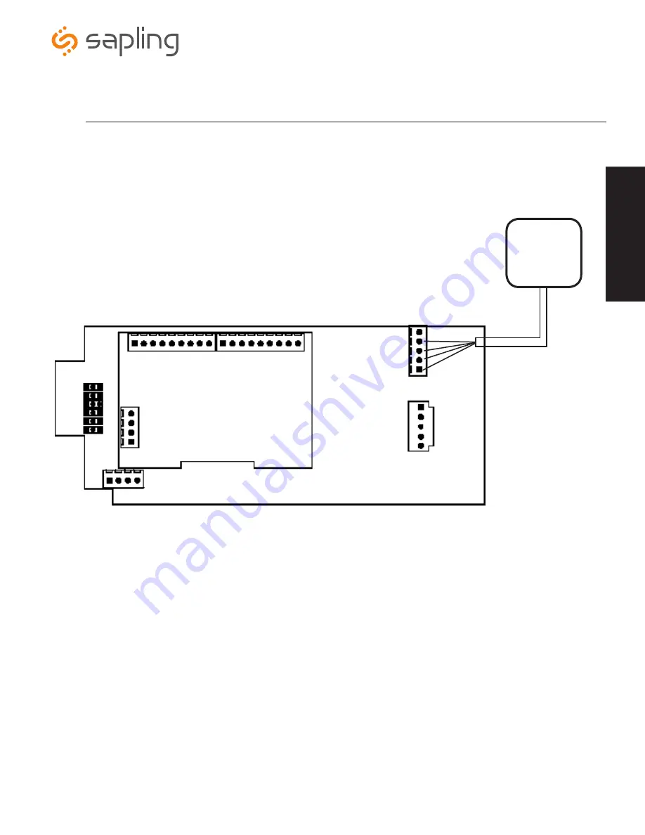
If you ordered a Temperature Sensor with your SBL 3200/3300 clock, it must be connected to a terminal on the Clock.
Connecting The Temperature Sensor
Temperature Sensor
Sensor Cable
(
IMPORTANT
: Detach clock from power source before installing new circuitry. DO NOT add new circuitry while the clock is operating)
Attach the end of the Temperature Sensor Wire to the circuit board in the following manner:
Data from the temperature sensor will be sent to your clock when the
clock is powered on. For more information on how to make the SBL
display temperature, please see the section labeled “Web Interface -
Display Settings”.
The Sensor Cable is 6 feet (1.83 meters) long, and so the sensor
should be positioned within 6 feet of the clock. The cable is
unshielded, 4 conductor, 22AWG (.33mm²). If longer than 6 feet is
required, the wire would have to be terminated in an electrical box,
and the longer wire would have to be provided by the customer.
1
2
3
4
5
5) No connection
4) White
3) Black
2) Green
1) Red
13
W
iri
ng
In
for
m
at
ion
Please Note:
The board depicted below is related to
the 3300 series digital clock. If you have purchased the
3200 series digital clock, the Temperature Sensor will
connect in the same manner.


