background image

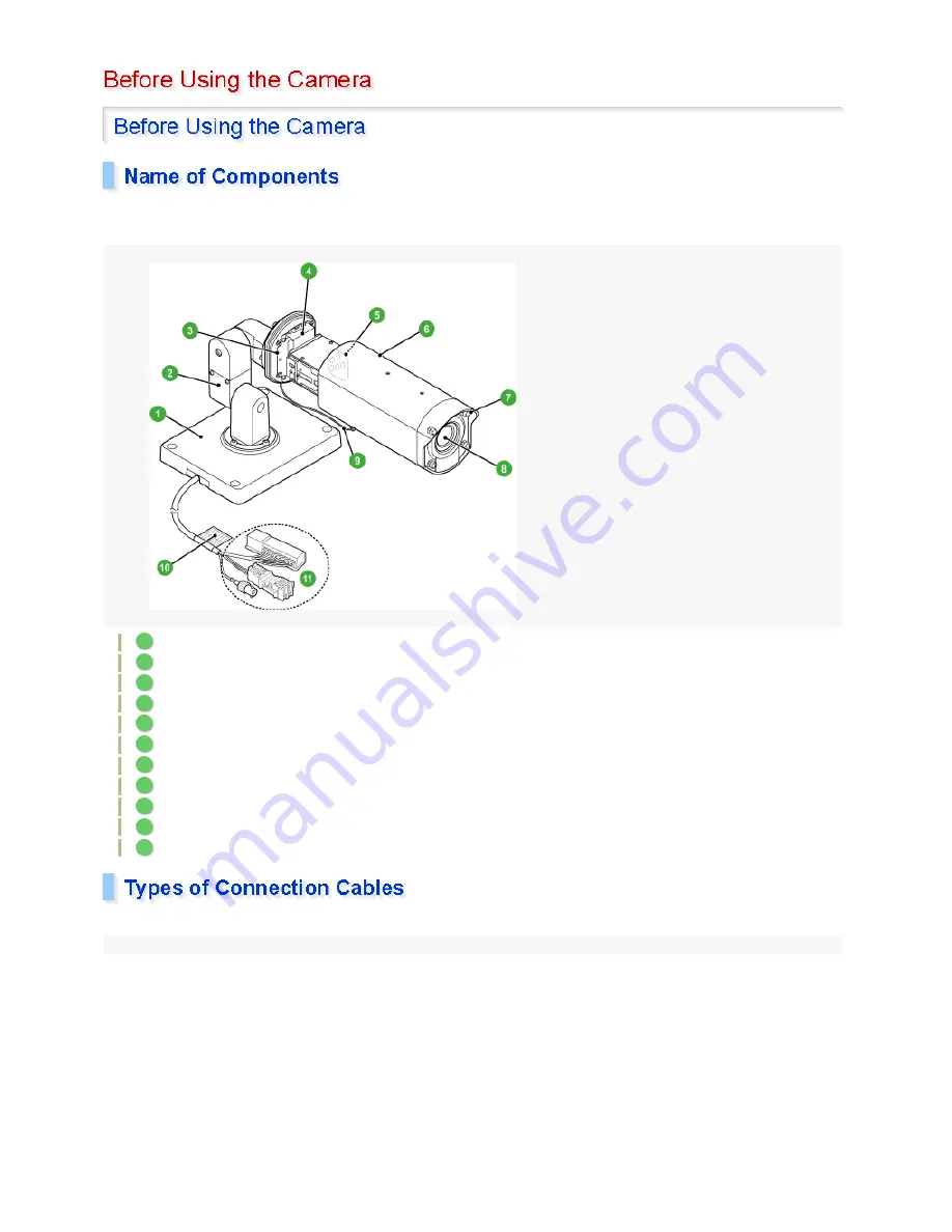
The figure below illustrates the system when the camera cover is pulled forward by loosening the camera cover 
fixing screws. 

Camera stand 
Arm 
Camera mount 
Camera mounting bracket 
Operation buttons (on right side face) 
Camera cover 
Camera cover fixing screws (×4) 
Lens 
Safety chain 
Cable label 
Connection cables 

You can identify each connection cable by its shape and color. 

1

2

3

4

5

6

7

8

9

10

11

1 / 153

Summary of Contents for VCC-XZN600P

Page 1: ...camera cover fixing screws Camera stand Arm Camera mount Camera mounting bracket Operation buttons on right side face Camera cover Camera cover fixing screws 4 Lens Safety chain Cable label Connection cables You can identify each connection cable by its shape and color 1 2 3 4 5 6 7 8 9 10 11 1 153 ...

Page 2: ...y switch between the color and black white modes select DAY NIGHT choose the COLOR mode and then set the EXT ALARM to an appropriate input level BLACK ALARM IN 2 BLUE ALARM OUT Used to connect a buzzer lamp video recorder or other peripheral device To control the alarm output externally from a remote location on the ALARM OUT screen select OUTPUT and choose REMOTE 3 LAN cable connector BLACK thick...

Page 3: ...ble is now locked Make sure that the cable is locked firmly in place 1 2 3 To prevent short circuiting make sure that the stripped wire portion is not exposed out of the connector This connector is a separable type Separating the connector by pressing the connector lever facilitates your work especially when changing the connection with the power supply A 3 153 ...

Page 4: ...es to the power terminals of the one touch connector Use a power cable with an AWG wire 20 21 or 22 Although power wires have no polarity in this case the earth wire must be connected to the earth COMMON terminal 1 Cable type RG 59U 3C 2V 250 m maximum Cable type RG 6U 5C 2V 500 m maximum Cable type RG 11U 7C 2V 600 m maximum Using lower grade cables will cause the attenuation of the video and syn...

Page 5: ...our PC Connect the following cables as required For detailed information on these connections refer to the separate installation manual ALARM IN cables GRAY BLACK BLACK Used to connect alarm switch infrared sensor or other external devices ALARM OUT cable BLUE Used to connect a buzzer lamp digital video recorder or other peripheral device FOCUS ZOOM cable YELLOW ORANGE Used to remote control the c...

Page 6: ...6 153 ...

Page 7: ...se SANYO products for connection with this camera Displays surveillance video for monitoring The monitor also displays the menu screen Records surveillance video For surveillance systems the use of a DVR is recommended DVRs ensure a long hour recording without video degradation 7 153 ...

Page 8: ...tton to set the value you adjusted or chose for the selected item or switch to the sub menu When the menu screen is not displayed the operation buttons can be used to perform the following operations Focus adjustment Use the button to set the focus to a near target After you complete setting up the camera reinstall the camera cover in position and tighten the fixing screws with a torque of 0 5 to ...

Page 9: ... target Zoom adjustment Magnification 1 to 30 Use the button to zoom out of the target Use the button to zoom into the target One push auto focus adjustment Use the SET button to focus the camera automatically by one push operation 2 3 9 153 ...

Page 10: ...modes depending on the luminance of the target 3 LENS FOCUS Sets the focusing mode ZOOM Sets the optical zooming speed and electronic zooming option 4 ALARM ALARM IN Provides alarm input settings ALARM OUT Provides alarm output settings ALARM DISPLAY Sets the alarm display function 5 PRIVACY MASK MASK 1 to 4 Masks anywhere you want to hide on the screen for the purpose of privacy protection 6 PASS...

Page 11: ...ight of the selected menu item press the SET button The next level sub menu or the details setting screen appears To choose a setting show the desired value or option using the button To return to the previous screen use the button to select MENU and with the setting of BACK shown press the SET button To close the menu screen use the button to select MENU use the button to change 1 2 3 4 5 11 153 ...

Page 12: ...END and press the SET button The main menu disappears and live video images appear on the screen To display the main menu again press the SET button located on the side face of the camera for approximately three seconds 12 153 ...

Page 13: ... settings for the following items PRIVACY MASK on main menu PASSWORD on the main menu DISPLAY TITLE and NETWORK on the OPTION menu Zoom or focus setting in POSITION on the CAMERA menu Note that the value of the item POSITION is reset from ON to the default OFF When the POSITION setting is switched to OFF the zoom and focus settings stored in the camera will be overwritten by those settings of the ...

Page 14: ...zation Performs synchronization according to the camera s internal signal L L Line Lock Power source synchronization Performs synchronization according to the frequency of the commercial power source With this method you can manually adjust the vertical synchronization phase 14 153 ...

Page 15: ...ct SYNC use the button to choose L L and press the SET button The L L SETTING screen appears Use the button to adjust the vertical synchronization phase Select MENU and choose BACK or END to complete adjustment 1 2 3 15 153 ...

Page 16: ... automatically detects moving targets POSITION setting Stores the zoom focus settings of the current position by camera setting number 1 or 2 DAY NIGHT setting Sets the Day Night function that automatically switches between color and black white video modes depending on the luminance of the target Setting example for using the operating conditions for the daytime use and nighttime use Select CAMER...

Page 17: ...RA on the main menu use the button to choose the camera setting number 1 or 2 with which you want to set operating conditions and press the SET button The CAMERA setting screen for the chosen camera setting number appears 1 17 153 ...

Page 18: ...ark to 100 bright Select MENU and choose BACK or END to complete adjustment The auto iris function is not available when the electronic iris EI is set Set the lens iris manually using the following procedure Use the button to select IRIS use the button to choose MANU and press the SET 1 2 If the electronic sensitivity boosting power cannot be set MOTION is set to ON or AGC is set to OFF Setting th...

Page 19: ...f the video signal level Available settings 0 dark to 100 bright Select MENU and choose BACK or END to complete adjustment 2 Setting the electronic iris EI causes the following The SHUTTER electronic shutter setting SHORT or LONG will be cancelled and the SENSE UP electronic sensitivity boosting will not work Under extremely bright lighting the electronic iris cannot adjust the light entering thro...

Page 20: ...on to choose ATW and press the SET button The ATW SETTING screen appears Select MENU and choose BACK or END to complete the setting To mask a specific light source or to set the SMART ATW function do the following If the target objects include an extremely bright light source set a mask as follows to correct the white balance Use the button to select MASKING use the button to choose ON and press t...

Page 21: ... balance may not produce desirable results if a single color occupies the majority of the images In such a case use the smart function Use the button to select SMART ATW and use the button to choose ON This sets the smart function To delete a mask move the mask pattern over it and press the SET button 3 4 Do not use the smart function in environments where the color temperature varies In an outdoo...

Page 22: ...tting changes from to highlighted in two seconds which indicates that the white balance adjustment has been completed Select MENU and choose BACK or END to complete adjustment You can set the color temperature to a fixed value Use the button to select WHITE BALANCE and use the button to choose the desired fixed white balance option Available settings 2 1 2 If the white balance adjustment does not ...

Page 23: ...B SETTING screen appears Use the button to select R or B and use the button to choose the gain value of the red or blue signal Available settings Select MENU and choose BACK or END to complete adjustment 3200 For indoors Fixes the color temperature to 3200 K 5600 For outdoors Fixes the color temperature to 5600 K FLUO For fluorescent lighting Fixes the color temperature to 4200 K 2 1 2 R red 0 lig...

Page 24: ...d use the button to adjust the backlight compensation weight sensitivity Available settings 0 low sensitivity to 15 high sensitivity Use the button to select BRIGHT and use the button to adjust the compensation level for the brightness of the backlighting Available settings 0 minimum brightness compensation to 15 maximum brightness compensation Select MENU and choose BACK or END to complete adjust...

Page 25: ...he SET button The BLC WINDOW WEIGHTING screen appears Use the button to select each spot to be weighted and use the button to set the weighting value Spot evaluative metering will occur in five spots TOP BOTTOM LEFT RIGHT and CENTER The weighting value of CENTER FIX is fixed to 7 Available settings 0 minimum to 7 maximum 2 3 Use the button to change the vertical size Use the button to change the h...

Page 26: ...t BLC use the button to choose MASK and press the SET button The BLC MASKING screen appears with a blinking mask pattern shown at the top left Use the buttons to move the mask pattern over the light source you want to mask and press the SET button This sets a mask at the position where you moved the mask pattern A new mask pattern starts blinking Repeat this step to set masks as many as you want 5...

Page 27: ...bottom area of the screen and press and hold the button for approximately three seconds The PRESET and MENU items appear on the screen Select MENU and choose BACK or END to complete the setting To delete a mask move the mask pattern over it and press the SET button 3 4 27 153 ...

Page 28: ...creasing the exposure time will improve the sensitivity ensuring clear images even if the target objects are dark Use the button to select SHUTTER use the button to choose LONG and press the SET button The ES SETTING screen appears If fast shutter speeds SHORT cannot be set SENSE UP electronic sensitivity boosting or EI electronic iris is set 1 2 PAL 50 120 250 500 1000 2000 4000 10000 NTSC 60 100...

Page 29: ...ttings Select MENU and choose BACK or END to complete the setting 2 1 2 4 8 16 32 The faster shutter speeds the longer the resulting exposure time Setting an excessively long exposure time may result in ghosts blurs and white spots in moving target objects 3 29 153 ...

Page 30: ...Use the button to select APERTURE use the button to choose ON and press the SET button The APERTURE SETTING screen appears Use the button to select the direction of aperture compensation H or V and use the button to set the compensation value Available settings Select MENU and choose BACK or END to complete the setting 1 2 H Horizontal aperture compensation 1 to 15 V Vertical aperture compensation...

Page 31: ...se Reduction will reduce the noise at low luminance levels Select MENU and choose BACK or END to complete the setting Use the button to select AGC use the button to choose OFF and press the SET 1 2 LOW For bright target object NORMAL Normal setting MIDDLE For slightly dark target objects HIGH For dark target objects The maximum gain value varies depending on the Day Night function mode Setting a h...

Page 32: ...e button to set the AGC s gain value Available settings 0 to 30 dB Select MENU and choose BACK or END to complete the setting If AGC cannot be set to OFF DAY NIGHT is set to AUTO or SENSE UP electronic sensitivity boosting is set to ON 2 3 32 153 ...

Page 33: ...rection level Available settings Select MENU and choose BACK or END to complete the setting 1 0 45 Sets the gamma correction level to 0 45 1 Sets the gamma correction level to 1 MODE1 Increases the contrast in dark areas MODE2 Increases the contrast in dark areas further Choosing MODE1 or MODE2 may result in excessively bright images depending on the target objects 2 33 153 ...

Page 34: ...T button The MOTION SIZE screen appears showing the detection pattern in the center area Use the button to select V for vertical sizing or H for horizontal sizing and use the button to set the size value The size of the detection pattern shown on the screen changes based on the V and H settings An alarm signal will be output if motion is detected in all areas of the set detection pattern Available...

Page 35: ... at the top left H Horizontal sizing 1 to 8 The maximum size of the detection pattern V x H is 9 If setting a vertical or horizontal size causes this maximum size to be exceeded the other size will be automatically adjusted The detection pattern can be set in 19 sizes as shown below Any motion in the target that is larger than the area of the set detection pattern causes the motion sensor to respo...

Page 36: ...tems and use the button to adjust the detection level For all items the sensitivity decreases as you increase the value MOVE Motion sensitivity 1 to 10 Set a larger value to prevent the detection of subtle movements such as those caused by a breeze Y LEVEL Brightness level 1 to 10 Set a larger value to prevent unwanted detection due to noise in a dark image Y DIFFER Brightness difference 1 to 10 S...

Page 37: ...alarm signal from detecting subsequent alarm motions for that period Use the button to select DURATION and use the button to choose the alarm disable duration Available settings 5S 10S 15S 20S 30S 45S 1M 2M 3M 4M 5M S seconds M minutes Select MENU and choose BACK or END to complete the setting 1 2 37 153 ...

Page 38: ...ot store zoom and focus settings set POSITION to OFF Use the button to adjust the zoom and use the button to adjust the focus and press the SET button This stores the zoom and focus settings and brings you back to the CAMERA setting screen 1 2 The button can be used to adjust the focus even when the auto focus is set FOCUS is set to AUTO When POSITION is set to OFF the zoom and focus settings stor...

Page 39: ... or see distorted images when the camera mode is switched This is not a malfunction however In AUTO mode turning OFF the camera with black white image displayed and then turning it back on again switches to color image The retrieved focused position may differ between the color and black white images When using infrared lighting in the black white mode the camera may switch to the color mode due t...

Page 40: ...nce Use the button to select BURST and use the button to turn ON OFF the burst signal If connected to a peripheral device like a frame switcher the camera may produce distorted images or burst when switching between the color and black white video modes This phenomenon can be corrected by inserting a color burst signal Normally set BURST to OFF Available settings Use the button to select FOCUS and...

Page 41: ... 2 alarm input channel set on the D N SETTING COLOR screen and use the button to select POLARITY For details see Setting the Alarm Input ALARM IN POLARITY NO Open color mode Closed black white mode POLARITY NC Open black white mode Closed color mode Select MENU and choose BACK or END to complete the setting 2 1 2 OFF Disables detection of external alarm input 1 Switches to color or black white mod...

Page 42: ...F Available settings Use the button to select FOCUS and use the button to choose the focus compensation mode Normally set the focus compensation mode to 1 However if the target gets out of focus set this to 2 Available settings Select MENU and choose BACK or END to complete the setting 1 2 ON Inserts a burst signal OFF Does not insert a burst signal 3 1 Use this mode if the camera is used under ne...

Page 43: ...cify the options for focusing and zooming operations Focusing operation settings FOCUS Sets the focusing mode to either auto or manual Zooming operation settings ZOOM Sets the optical zooming speed and electronic zooming option 43 153 ...

Page 44: ...ct LIMIT NEAR and use the button to choose the nearest focusing distance to the object Available settings 10cm 30cm 50cm 1m 3m 5m Use the button to select SENSITIVITY and use the button to select sensitivity in focusing Available settings 1 2 3 When the distance to the object is less than or equal to 1m focusing may become difficult 4 HIGH High sensitivity focusing LOW Low sensitivity focusing Whe...

Page 45: ... Available settings Select MENU and choose BACK or END to complete the setting Use the button to select FOCUS use the button to choose MANU and press the SET button The FOCUS SETTING screen appears 5 6 1 entire screen 2 center of screen larger area 3 center of screen smaller area 7 8 AUTO Returns the focusing mode automatically to the auto focus mode when a zooming operation is performed after the...

Page 46: ...ble settings 10cm 30cm 50cm 1m 3m 5m Use the button to select SPEED and use the button to select the focusing speed Available settings 1 2 3 and 4 maximum Select MENU and choose BACK or END to complete the setting 2 When the distance to the object is less than or equal to 1m focusing may become difficult 3 4 46 153 ...

Page 47: ...s Available settings Use the button to select V RESO UP and use the button to enable disable the vertical resolution increase Available settings Select MENU and choose BACK or END to complete the setting 1 2 3 OFF Optical zoom only x 2 Approx 60x magnification x 4 Approx 120x magnification x 8 Approx 240x magnification x 16 Approx 480x magnification When the electronic zoom is applied the quality ...

Page 48: ...o perform the alarm input settings input conditions alarm action etc for each alarm input number ALARM OUT Allows you to perform the alarm output settings ALARM DISPLAY When an alarm is detected the camera title displayed in the screen blinks indicating that an alarm is detected 48 153 ...

Page 49: ...isplay duration ZOOM TIME To use this setting select whether or not to return to the previous operating conditions upon completion of an alarm action in RETURN under the item ACTION 1 2 When the alarm input is used as the external control input of the DAY NIGHT function D N appears in the top right of the screen In this case settings other than POLARITY cannot be made When EXT ALARM for DAY NIGHT ...

Page 50: ... to set the duration for which the zoomed image is displayed Available settings 5S 10S 15S 20S 30S 45S 1M 2M 3M 4M 5M S seconds M minutes 1 2 Use the button to choose MANU and press the SET button The RATIO SETTING screen appears On this screen the and buttons are used for zooming operation and the and buttons for focusing operation Use the button to adjust the zoom and use the button to adjust th...

Page 51: ...an alarm input source 1 CAM1 Uses the operating conditions you configured for Camera 1 in CAMERA to monitor surveillance points CAM2 Uses the operating conditions you configured for Camera 2 in CAMERA to monitor surveillance points 2 OFF Retains the operating conditions used after the receipt of the alarm input ON Returns to the operating conditions before the receipt of the alarm input Setting RE...

Page 52: ... M minutes Select MENU and choose BACK or END to complete the setting AND Both the motion sensor and the external device detect an alarm condition OR Outputs an alarm signal if the motion sensor detects an alarm condition or an external alarm input is received 5 OFF Does not output the alarm signal ON Outputs the alarm signal 6 OFF Does not output the alarm signal ON Outputs the alarm signal 7 The...

Page 53: ... M minutes Select MENU and choose BACK or END to complete the setting 1 2 ON Outputs the alarm signal OFF Does not output the alarm signal REMOTE Outputs the alarm signal by remote operation When selecting REMOTE MANU is available for ALARM TIME enabling remote operation of the alarm output using an external device Selecting AUX6 ON enables remote operation and selecting AUX6 OFF disables remote o...

Page 54: ...settings 5S 10S 15S 20S 30S 45S 1M 2M 3M 4M 5M S seconds M minutes Select MENU and choose BACK or END to complete the setting 1 OFF The alarm information does not blink ON When an alarm is detected the camera title displayed in the screen blinks indicating that the alarm is detected While ALARM DISPLAY is set to ON the camera title will flash even when TITLE in DISPLAY is set to OFF If the camera ...

Page 55: ...rtain part of the surveillance image The privacy mask may be used to protect privacy Up to 4 privacy masks can be set Setting the Privacy Mask over Areas You Want to Hide Turning Configured Privacy Masks On Off and Reconfiguration Masks 55 153 ...

Page 56: ... be covered and press the SET button The MASK 1 SET SIZE screen appears Use the buttons to adjust the vertical and horizontal sizes of the mask pattern and press the SET button This completes the privacy mask settings The MASK NO SELECT screen appears again and the setting for MASK 1 has been changed to ON Repeat the same procedures above to set MASK 2 to MASK 4 as necessary 1 2 3 4 5 If any other...

Page 57: ...Select MENU and choose BACK or END to complete the setting numbers which appear in masking order from left to right 6 57 153 ...

Page 58: ...re SET the mask Available settings You can display up to 4 privacy masks simultaneously on the screen if you turn on all the privacy masks MASK 1 to 4 ON Displays the privacy mask for the mask number you selected OFF Does not display the privacy mask for the mask number you selected SET Resets the privacy mask setting 58 153 ...

Page 59: ... by password entry PASSWORD CHANGE Changes the password The factory setting value of the password is 1234 For security reasons change your password periodically When the password lock is set entering the password is prompted before performing any menu operation While this option is set to ON only the password administrator can change the menu settings 59 153 ...

Page 60: ...this procedure until the whole password value ex 1234 is entered and press the SET button When a valid password is entered OK appears Press the SET button again This completes the password lock setting and the PASSWORD screen appears again While the password lock is enabled ON is displayed for PASSWORD LOCK Select MENU and choose BACK or END to complete the setting 1 2 3 When a wrong password is e...

Page 61: ...61 153 ...

Page 62: ...procedure until the whole password value is entered and press the SET button When the valid password is entered OK appears When a wrong password is entered NG appears Press the SET button again This disables the password lock function and the PASSWORD screen appears again When the password lock is disabled OFF is displayed for PASSWORD LOCK Select MENU and choose BACK or END to complete the settin...

Page 63: ...lue ex 1234 is entered and press the SET button When the valid password is entered the PASSWORD NEW PASSWORD screen appears Use the button to select the digit and use the button to select a number for the digit Repeat this procedure until the new password value ex 4321 is entered and press the SET button OK appears under the NEW PASSWORD field and the new password is set Select MENU and choose BAC...

Page 64: ...button The LANGUAGE screen appears Use the button to select the language used for menu display and press the SET button All the menu displays are changed to the selected language Available settings Select MENU and choose BACK or END to complete the setting 1 2 PAL system region English French German NTSC system region English French Spanish 3 64 153 ...

Page 65: ... their position in the monitor MIRROR Sets a mirroring mode according to your installation condition of the camera This setting is useful for example when the camera is installed upside down or when performing surveillance through a mirror STABILIZER Corrects images from a shaking camera installed on the roadside or a similar place NETWORK Sets the communication conditions when you connect the cam...

Page 66: ... want the camera title and the zoom magnification power to be displayed on the monitor Use the button to select TITLE use the button to choose ON and press the SET button The camera title setting screen appears Use the buttons to select a character for the title from the character selection panel and press the SET button The selected character C in the example below appears in the first digit of t...

Page 67: ...Use the button to select ZOOM RATIO use the button to choose ON and press the SET button The current zoom magnification power appears in the right bottom corner of the screen The camera title can use up to 16 characters indication for the unused digits will not be displayed in the monitor 2 in the character selection panel represents the carriage return character When the character is entered the ...

Page 68: ...n power to be displayed and press the SET button The DISPLAY screen appears again Select MENU and choose BACK or END to complete the setting 2 If the display positions of the camera title and the zoom magnification power overlap the camera title precedes in display 3 68 153 ...

Page 69: ...he SET button For example an image will be rotated vertically and horizontally when HV is selected Available settings Select MENU and choose BACK or END to complete the setting 1 OFF Normal image HV Rotated vertically and horizontally H Rotated horizontally V Rotated vertically 2 69 153 ...

Page 70: ...nd choose BACK or END to complete the setting 1 2 The higher the correction level the lower the image resolution during correction The angle of view will also be slightly narrower The correction function will not work in the following condition During switching images between color and black white modes when using the Day Night function When the menu screen is displayed Immediately after powering ...

Page 71: ...button to select IP ADDRESS and press the button The IP ADDRESS setting screen appears Use the button to select the digit and use the button to enter the number and press button Repeat the procedure until the entire address is entered The IP ADDRESS SETTING screen appears again Perform settings for SUBNET MASK and GATEWAY using the same procedure for IP 1 2 FIX Assigns the IP address manually AUTO...

Page 72: ...PORT and press the button to set the port number used for network connection The same procedure used on the IP ADDRESS SETTING screen can be used to set the port number Use the button to select the digit and use the button to enter the port number and press the button Use the button to select ALARM OUT and enable disable the alarm output by selecting ON OFF To output the alarm signal to the networ...

Page 73: ...cus LENS FOCUS When the object is too bright When the object is dark When the object is hard to see in the backlight condition CAMERA BLC When proper white balance adjustment cannot be made CAMERA WHITE BALANCE Recording fast moving object CAMERA SHUTTER SHORT Emphasizing the profile of the object CAMERA APERTURE Adjusting the brightness or contrast level of the entire image CAMERA GAMMA When the ...

Page 74: ...r screen The live image can be displayed reversely by setting a mirroring mode according to your installation condition of the camera This mode is useful for example when the camera is installed upside down or when performing surveillance through a mirror You can display the camera s name on the monitor by setting a specific title to the camera 74 153 ...

Page 75: ...ge the zooming speed for optical zoom function the SPEED option While zooming operation is achieved by the optical lens mechanism you can zoom in the object further by setting the electronic zooming function 75 153 ...

Page 76: ...to zoom in the object automatically when the alarm is detected There are 15 available options for the magnification power in zooming You can configure the camera title to blink on the screen when the alarm is detected You can adjust the detection sensitivity to movement or brightness of the object 76 153 ...

Page 77: ...perture opening value CAMERA IRIS Select MIDDLE or HIGH for the MAX GAIN setting under the AGC option CAMERA AGC Set the electronic shutter setting to slow shutter speed LONG CAMERA SHUTTER Increase the level of electronic sensitivity SENSE UP CAMERA IRIS Adjust the iris level or the aperture opening value CAMERA IRIS When noise occurs in the image because the object is dark enable the digital noi...

Page 78: ... auto white balance function by setting SMART ATW to ON Although the camera is set to the auto trace white balance ATW mode by default you may choose to set other adjustment modes Set the electronic shutter to the fast mode SHORT Enable the profile compensation function Adjust the gamma correction level Set the sensitivity in focusing LOW in SENSITIVITY Compensate the black white video signal by i...

Page 79: ...79 153 ...

Page 80: ...t network communication conditions including the IP address for the camera Perform the input setting for the control terminal ALARM IN Perform the output setting for the control terminal ALARM OUT 80 153 ...

Page 81: ...ming of switching or fix the viewing mode to either the color or black white video modes change the option for the DAY NIGHT setting You can save two monitoring condition settings and select the setting according to the installation environment of the camera Use the password lock function While the password lock function is enabled the menu operations cannot be made unless the valid password is en...

Page 82: ... is selected for IRIS 2 The SHORT and LONG options cannot be selected for the SHUTTER setting 3 The auto gain control AGC cannot be set to OFF 4 The motion sensor option MOTION cannot be set to ON 5 The V RESO UP option in the ZOOM SETTING screen cannot be set to ON 6 The settings in the ALARM IN screen cannot be made 7 The setting you made has been forced to be changed 82 153 ...

Page 83: ...option MOTION is set to ON The fast shutter speed SHORT can be set 1 The SENSE UP setting cannot be made while AUTO is selected for IRIS In the following conditions the SENSE UP option is fixed to OFF and the level of electronic sensitivity cannot be configured 1 2 2 The SHORT and LONG options cannot be selected for the SHUTTER setting In the following conditions the SHUTTER option is fixed to OFF...

Page 84: ...hen the Day Night function DAY NIGHT is set to AUTO 3 The auto gain control AGC cannot be set to OFF In the following conditions the AGC option is fixed to ON and the auto gain control cannot be disabled 1 2 4 The motion sensor option MOTION cannot be set to ON 84 153 ...

Page 85: ...TTER is set to LONG When ON is selected for AGC and the digital noise reduction DNR is set to ON In the following conditions the MOTION option is fixed to OFF and the motion sensor functions cannot be configured 1 2 5 The V RESO UP option in the ZOOM SETTING screen cannot be set to ON In the following conditions the V RESO UP option is fixed to OFF and the vertical resolution increase cannot be co...

Page 86: ...to OFF 6 The settings in the ALARM IN screen cannot be made When the DAY NIGHT option is set to COLOR and the EXIT ALARM option is set to other than OFF 1 or 2 D N is displayed in the top right corner of the ALARM IN screen and the menu settings other than the POLARITY option cannot be made 7 The setting you made has been forced to be changed When you made the following setting other relevant sett...

Page 87: ...MANU is selected for IRIS and the electronic iris EI option is set to ON When SHORT or LONG is selected for the SHUTTER setting the option is changed to OFF When the Day Night function DAY NIGHT is set to AUTO When the AGC option is set to OFF the option is changed to ON When ON is selected for AGC and the digital noise reduction DNR is set to ON 87 153 ...

Page 88: ...When the V RESO UP option in the ZOOM SETTING screen is set to ON the option is changed to OFF 88 153 ...

Page 89: ...e Aperture compensation ON Horizontal and Vertical compensation settings adjustable and OFF Gamma correction 0 45 1 MODE1 Increases contrast and MODE2 Increases contrast further Electronic shutter Fast shutter speeds SHORT NTSC 1 60 1 100 1 250 1 500 1 1000 1 2000 1 4000 and 1 10000 PAL 1 50 1 120 1 250 1 500 1 1000 1 2000 1 4000 and 1 10000 Slow shutter speeds LONG x1 x2 x4 x8 x16 and x32 Camera ...

Page 90: ...Weight Without sunshade Approx 1 8 kg With sunshade Approx 2 0 g 90 153 ...

Page 91: ...subsidiaries in the United States and other countries IBM and IBM PC AT are trademarks of International Business Machines Corporation UPnP is a trademark of UPnP Implementers Corporation which is established by the UPnP Forum SC Java is a trademark of Sun Microsystems Inc All other brands and product names in this manual are the registered trademarks or trademarks of their respective owners PC IBM...

Page 92: ... camera and are authenticated by password during the login process The operations that the user can perform for the camera depend on the user name used to access the camera Up to 16 users can access the camera simultaneously 1 2 3 4 5 You can change the settings stored on the camera through network operations User name Operation privileges Password Default value guest Used for general users The gu...

Page 93: ...a Whatever the number of users accessing the camera simultaneously only one user can access the camera as an administrative user admin Live video image updates may be delayed depending on your system environment as the number of users simultaneously accessing the camera increases 93 153 ...

Page 94: ... Connections screen appears The LAN interface Ethernet adapter configurations appear in the LAN or High Speed Internet section Right click on the LAN interface Ethernet adapter configuration used for accessing the camera and click Properties in the context menu General tab appears in the Local Area Connection 2 Properties dialog box In the This connection uses the following items list box select t...

Page 95: ...he Use the following IP address radio button and complete the IP address Subnet mask and Default gateway fields Confirm the settings and click the OK button This completes the TCP IP settings Close all dialog boxes in the display Web browser is required to access the camera Install Internet Explorer Ver 6 0 or higher on your PC In the cases below perform the Internet Explorer s settings by clickin...

Page 96: ...ptions Click the General tab Under the Temporary Internet Files section click the Settings button In the Amount of disk space to use setting set the lower value Click the Advanced tab Under the Browsing section disable the Display a notification about every script error option Enable the Disable script debugging option 1 2 1 2 3 1 2 3 96 153 ...

Page 97: ...sword fields and click the OK button When accessing the camera for the first time use the factory setting values below Using these values you will be logged in as an administrative user User name admin Password admin After the values for the User name and Password fields are validated the language selection screen appears Select the language used for display Available languages 1 When Internet Exp...

Page 98: ...k the OK button The UPnP component title in the list should be either Universal Plug and Play or UPnP User Interface depending on your PC After the camera is turned on it will take about 1 minute for the camera to be available for accepting any accesses When you specify the port number for the camera to a number other than 80 add colon and the port number after the IP address in specifying the URL...

Page 99: ...n the My Network Places window The icon for the camera detected on the network appears in the window Double click the icon This establishes the connection to the camera and the authentication dialog appears Display name in the My Network Places window SANYO Camera camera title In the camera title section above the title specified for the camera in TITLE field of the NETWORK SETTINGS screen appears...

Page 100: ...ogin the display type can be switched with the selection button on the control panel ActiveX is characterized by its higher baud rate smooth motion in video and reduced file size Do not enable the screensaver while the ActiveX screen is being displayed If you encounter any trouble as a result of using screensaver restart your Web browser HTML screen 100 153 ...

Page 101: ...creen White Normal Red Buffering alarm data Detecting an alarm condition Transmitting an alarm Orange Waiting for the alarm images to be transmitted When the camera title is in red or orange no other alarms will be processed Once the alarm image has been sent or five minutes have passed with no alarm image sent the camera title returns to normal display white When the setting for the camera title ...

Page 102: ...d Used to control the alarm output from the camera remotely Click this button to terminate the connection to the camera and close the screen Some parts of the control panel and the remote alarm button are not displayed for the guest users 102 153 ...

Page 103: ...ol panel For the guest users only parts of the control panel are displayed Specifications of the control panel vary depending on the screen display types ActiveX HTML Use these buttons to display the camera s setting menu and change the camera settings from the menu remotely Performs the one push auto focus function 103 153 ...

Page 104: ... function corresponding to the number selected in the pull down menu will be performed The function When the electronic zoom function EL ZOOM is enabled on the camera and the zoom magnification reaches the maximum value of optical zoom x30 clicking the button further activates the electronic zoom function You can zoom in and out with the mouse wheel on the ActiveX screen Perform the following oper...

Page 105: ...es the image compression format between H 264 and JPEG Switches the streaming type between UNI and MULTI To select the ActiveX make sure that the H 264 plug in has been installed from the supplied CD ROM onto the PC When the image compression format is H 264 and MULTICAST SET on the CODEC STREAMING SETTINGS screen is set to ON the streaming type selection button is displayed 105 153 ...

Page 106: ...the still image and click the desired command in the context menu To close the window displaying the still image click Close When the ALARM OUT option is set to REMOTE on the camera you can operate the alarm output remotely Clicking the alarm remote button initiates the alarm output After the duration specified in the setting on the camera the output stops automatically While the ALARM OUT is bein...

Page 107: ...ings before starting the camera operation through the network Used for configuring the image and streaming settings of the video transmitted from the camera Used for configuring the automatic e mail transmission function The function allows you to receive the alarm notification e mail when the alarm condition is detected or to receive the e mails at a certain interval In either case the image can ...

Page 108: ...his menu is also used to set a desired date as holiday Used for updating the firmware or resetting all the values to the factory settings Displays the description menu for various functions on the HELP screen Click the HELP button to check the operating instructions Returns to the main screen displaying the live video For details on the setting preferences factory settings and restriction on the n...

Page 109: ...FIX enter the subnet mask When the IP ADDRESS setting is FIX enter the gateway If you specify an invalid value such as a double byte character the PLEASE ENTER A VALID VALUE warning dialog box appears If the dialog box is left open for a certain period of time clicking OK in the dialog box automatically switches the display to the language selection screen FIX Manually configure the IP address Ent...

Page 110: ...iginal settings click the CANCEL button before clicking the SET button FIX Manually configure the IP address Enter the IP address DHCP Automatically allocates the IP address If you see the warning message pop up saying This page contains both secure and nonsecure items you can make it undisplayed by performing the following steps Open the Internet Options dialog box on Internet Explorer click the ...

Page 111: ...w On the SECURITY SETTINGS screen you can configure the security function and set the camera access restriction to the PC Displays the HELP screen in a separate window For detailed information on the network settings contact your network administrator 111 153 ...

Page 112: ...cify the IP ADDRESS and SUBNETMASK 8 32 of the PC to which the access restriction is set individually Up to 10 PCs can be registered Sets the access restriction to the registered PCs individually When all the settings on the SECURITY SETTINGS screen are completed click the SET button to save the settings REJECTED Rejects the access from the PC that is not registered AUTHORIZED Allows the access fr...

Page 113: ...re the original settings click the CANCEL button before clicking the SET button Closes the SECURITY SETTINGS screen to returns to the NETWORK SETTING screen Displays the HELP screen in a separate window 113 153 ...

Page 114: ...LARGE of the date and time display in the ActiveX screen POSITION Sets the position UP LEFT UP RIGHT DOWN LEFT DOWN RIGHT of the date and time display in the ActiveX screen Sets the date and time display format Y M D M D Y D M Y Selects the area where the camera is used The days of week are automatically displayed based on date time setting The default date and time display in DAYLIGHT SAVING ON O...

Page 115: ... you change the setting on the TIME ZONE or DAYLIGHT SAVING MODE SUMMER TIME MODE preference the connection will be automatically disconnected and after about 30 seconds it will be established again The default date and time display in DAYLIGHT SAVING ON OFF automatically changes according to the area that is selected here 6 NO USE Disables the daylight saving mode USE Enables the daylight saving ...

Page 116: ...To restore the original settings click the CANCEL button before clicking the SET button Displays the HELP screen in a separate window 116 153 ...

Page 117: ...uest A motion of objects is detected by the change in brightness The DFFC may not work when the change in brightness is too small Under the following situation and or depending on the settings for the resolution and the picture quality JPEG images may not be provided in the specified frame rate Buffering alarm data Multiple users are accessing While distributing H 264 images in multicast When MULT...

Page 118: ...the range of 1025 to 65535 MULTICAST TTL Specify a numeric value in the range of 0 to 255 After completing the settings click this button to confirm the settings While other users are viewing H 264 images VBR Variable bit rate CBR Constant bit rate Do not specify the following values to the transmission port from 4000 to 5000 10000 10001 and 38214 49152 reserved for UPNP port cannot be set The mul...

Page 119: ...Up to 8 users when the resolution is 176 x 144 UDP Multicast The number of users who can access simultaneously is not limited If the multicast setting is turned ON on multiple cameras however assign a separate IP address or port number to each camera Video image will not be displayed properly when multiple cameras are assigned the same IP address port number When H 264 images are distributed with ...

Page 120: ...ese setting items SMTP SERVER ADDRESS domain name or IP address SMTP PORT NUMBER port number used for communicating with the SMTP server For the details consult your network administrator Specifies the sender s e mail address When you specify the domain name also specify the DNS of your network 120 153 ...

Page 121: ...UBJECT Specifies the e mail subject up to 32 characters displayed at the top of the e mail message TEXT Specifies your additional comment up to 64 characters appended after the default information Specifies the preferences for sending notification e mail using the timer E mails are sent automatically at the interval specified in TX RATE 1 2 File name of the attached image CAMERA ID yymmddhhmmss _0...

Page 122: ...ject up to 32 characters displayed at the top of the e mail message TEXT Specifies your additional comment up to 64 characters appended after the default information Specifies the interval for sending notification e mails The log of SMTP e mail transmission is displayed After completing the settings click this button to confirm the settings To restore the original settings click the CANCEL button ...

Page 123: ...to the recording playing software VA SW3050 which is optionally available FTP Transfers the image to the FTP server When you record and play video in the HTTP mode configure the recording conditions on the screen of VA SW3050 When the alarm settings are performed in the VA SW3050 the IMAGE TRANSMISSION setting on this screen is automatically set to the HTTP The FTP cannot be selected 123 153 ...

Page 124: ... is detected only the post alarm images will be transferred to the VA SW3050 software The transfer speed depends on the network environment After completing the settings click this button to confirm the settings To restore the original settings click the CANCEL button before clicking the SET button Displays the HELP screen in a separate window 1 2 PRE POST Configures the recording capacity ratio b...

Page 125: ...ort number configured on the server Normally 21 is set SERVER ADDRESS USER ID PASSWORD FTP PASSIVE Configures the operating conditions and camera ID for alarm image transmission Do not specify the following values to the transmission port from 4000 to 5000 10000 10001 and 38214 When you specify the domain name also specify the DNS of your network 1 125 153 ...

Page 126: ... is configured one image at a time is automatically transmitted at the interval that was set in TX RATE TIMER Specifies the preferences for image transmission using the timer OFF Disables the alarm image transmission ON Enables the alarm image transmission SCHEDULE Sends the alarm image only during the scheduled time You cannot use the following letters for CAMERA ID single quotation double quotat...

Page 127: ...ing the scheduled time You cannot use the following letters for CAMERA ID single quotation double quotation backslash slash colon and semicolon If the CAMERA ID is not configured sanyo and timer are substituted as the file name and folder name respectively OFF Stores all files without conducting overwrite date and time information is displayed in the file name ON Overwrites date and time informati...

Page 128: ...gistered domain name before user ddns sanyosecurity com The DDNS server name is displayed automatically you don t need to enter it members ddns sanyosecurity com They are displayed automatically As they are required to register the domain name write down them before accessing the SANYO s DDNS service site The access interval to the server is automatically set to 10MIN The log of one DDNS update hi...

Page 129: ...ame and password are displayed automatically in USER NAME and PASSWORD respectively Write down the user name and password They are required to register the domain name Click the REGISTER button Clicking the button automatically accesses the SANYO s DDNS service site and the LOG IN screen appears https www ddns sanyosecurity com Enter the USER NAME and PASSWORD which you have written down in step 2...

Page 130: ...ed in the DDNS server Return to the DDNS SETTINGS screen and input the registered domain name in DOMAIN NAME 5 3 When you use the DDNS service port forwarding must be set on your router For details on how to set port forwarding please refer to your router s instruction manual 130 153 ...

Page 131: ...of the week Specify the duration the start and end time for activating the function When the end time is earlier than or equal to the start time the duration specified extends to the next day and the day of the week displayed for the end time changes to the next day The specified schedule can be applied to the following five functions TIMER SMTP Enable disables the e mail transmission using the ti...

Page 132: ...MAGE TRANFER SETTINGS screen Displays the HELP screen in a separate window The auto mode function operates the camera at the scheduled time automatically according to the specified operation pattern You can specify up to two auto mode operation patterns per day OFF Disables the function ON Performs the function according to the schedule 2 The alarm image transmission and timer transmission in the ...

Page 133: ...nt to treat as holidays If you want to enable the same schedule setting to be applied to every day select DAILY at the bottom of the column and specify the details COMMAND Registration number PRESET 1 8 AUX ON 1 16 AUX OFF 1 16 When both the day of the week checkbox SUN SAT and the DAILY checkbox are selected the earlier start time setting precedes If the start time settings are same for both chec...

Page 134: ...dless of the actual day of the week the same operation schedule as the day of the week specified in HOLIDAY will be applied You can specify up to 20 dates as holiday When all the settings in the SCHEDULE SETTINGS screen are completed click the SET button to save the settings To restore the original settings click the CANCEL button before clicking the SET button 134 153 ...

Page 135: ...ur PC After you change the UPnP settings use the Close button to terminate the camera connection and access the camera again After you change the UPnP setting from ON to OFF take a note of the camera s IP address shown in the NETWORK SETTINGS screen so that you can access the camera from the Web browser Neither make any operations on the screen nor turn power off while the LOADING FIRMWARE FILE me...

Page 136: ...ration process is completed the camera is disconnected automatically and then connected again automatically in 40 seconds Saves the setting information of the camera Click the SAVE button and select the SAVE on the save confirmation dialog box Then specify the destination for storing the setting information Reloads the saved setting information of the camera to restore the original settings Click ...

Page 137: ...dly to switch the value until the desired value is displayed To open the submenu Menu items with mark have a submenu for detailed settings Move the cursor to your desired menu and click to open the submenu To return to the previous screen Click to move the cursor to MENU at the bottom of the submenu set the value to BACK and click To exit from the menu Click to move the cursor to MENU at the botto...

Page 138: ... on the value set on the camera AUX 1 16 ON OFF Setting menu Options TITLE Network Camera up to 16 alphanumeric characters IP ADDRESS FIX 192 168 0 2 DHCP SUBNET MASK 255 255 255 0 GATEWAY 192 168 0 1 DNS FIX DHCP DNS SERVER ADDRESS 0 0 0 0 SSL OFF ON PORT NUMBER SSL OFF 80 SSL ON 443 PASSWORD 4 8 User name guest guest 4 to 8 alphanumeric characters User name admin admin 4 to 8 alphanumeric charac...

Page 139: ...ST SET OFF ON UDP Multicast IP 239 UDP Multicast PORT 34344 MULTICAST TTL 16 0 255 Setting menu Options SEND MESSAGE OFF ON SMTP SERVER ADDRESS up to 64 characters SMTP PORT NUMBER 25 USER MAIL ADDRESS up to 64 characters RECIPIENT MAIL ADDRESS up to 64 characters AUTHENTICATION NO USE POP3 SMTP USER ID up to 48 characters PASSWORD up to 20 characters POP3 SERVER ADDRESS up to 64 characters ALARM ...

Page 140: ... BASIC NORMAL ENHANCED FINE SUPER FINE BUFFER SIZE OFF 0 5MB 1MB 2MB 4MB 6MB 8MB PRE POST 0 100 10 90 20 80 30 70 40 60 50 50 RATE NTSC 1ips 2ips 3ips 5ips 10ips 15ips 30ips PAL 1ips 2ips 3ips 5ips 8ips 12 5ips 25ips DURATION 5SEC 10SEC 20SEC 40SEC 1MIN 2MIN 3MIN 4MIN 5MIN 10MIN 15MIN TX RATE 1SEC 2SEC 3SEC 5SEC 10SEC 20SEC 40SEC 1MIN 2MIN 3MIN 4MIN 5MIN 10MIN 15MIN TIMER TIMER OFF ON SCHEDULE CAM...

Page 141: ...AUX ON 1 16 AUX OFF 1 16 HOLIDAY SETTINGS HOLIDAY SUN MON TUE WED THU FRI SAT MONTH DAY MONTH JAN FEB MAR APR MAY JUN JUL AUG SEP OCT NOV DEC DAY 01 to 31 Setting menu Options UPnP ON OFF Setting menu Options SECURITY FUNCTION ON OFF DEFAULT POLICY REJECTED AUTHORIZED NETWORK ADDRESS SUBNET REJECTED AUTHORIZED 141 153 ...

Page 142: ...of this software must display the following acknowledgment This product includes software developed by the OpenSSL Project for use in the OpenSSL Toolkit http www openssl org 4 The names OpenSSL Toolkit and OpenSSL Project must not be used to endorse or promote products derived from this software without prior written permission For written permission please contact openssl core openssl org 5 Prod...

Page 143: ...n the code are not to be removed If this package is used in a product Eric Young should be given attribution as the author of the parts of the library used This can be in the form of a textual message at program startup or in documentation online or textual provided with the package Redistribution and use in source and binary forms with or without modification are permitted provided that the follo...

Page 144: ...ITUTE GOODS OR SERVICES LOSS OF USE DATA OR PROFITS OR BUSINESS INTERRUPTION HOWEVER CAUSED AND ON ANY THEORY OF LIABILITY WHETHER IN CONTRACT STRICT LIABILITY OR TORT INCLUDING NEGLIGENCE OR OTHERWISE ARISING IN ANY WAY OUT OF THE USE OF THIS SOFTWARE EVEN IF ADVISED OF THE POSSIBILITY OF SUCH DAMAGE The licence and distribution terms for any publically available version or derivative of this cod...

Page 145: ...0ips 720 480 PAL Max 25ips 720 576 H 264 NTSC Max 30ips 720 480 PAL Max 25ips 720 576 Bandwidth 128 256 512 Kbps 1 2 3 4 Mbps no limitation Alarm buffer Up to 8 MB configurable Interface Ethernet 10BASE T 100BASE TX RJ45 connector Communication method TCP IP UDP HTTP HTTPS SMTP NTP DHCP FTP UPnP DDNS Simultaneous access capacity Maximum 16 users admin 1 user Security BASIC authentication ID passwo...

Page 146: ...urst Signal BURST Aperture APERTURE Coaxial Superimposed Communication COAX RS 485 Communication 485 Address ADDRESS Protocol PROTOCOL Baud Rate BAUD RATE Terminator TERMINATE SSP Security Serial Protocol IP Address IP ADDRESS Port Number PORT DHCP Dynamic Host Configuration Protocol Subnet Mask SUBNET MASK Gateway GATEWAY IP66 146 153 ...

Page 147: ...ral as possible The luminosity of the monitor screen changes according to the strength of signal input from the camera The numerical value showing the level change of luminosity according to the strength change of signal input is called gamma value The level of luminosity does not change in proportion to the strength of input signal The changes of the level and strength are expressed with a curve ...

Page 148: ... the compensation level of the camera to LOW MIDDLE or HIGH according to the blurring level of the camera When a compensation level is set for the camera the electronic zoom will expand the image i e the angle of view will change With the level set to HIGH the angle of view will become the narrowest when the level of compensation is the greatest and the sway of the image will be suppressed most ef...

Page 149: ...HIGH about 1 2x MIDDLE about 1 1x 149 153 ...

Page 150: ... The DNR is a function that discriminates and removes only the noise from the brightness and color signals of the image thus reproducing a beautiful high quality image A color sync signal required for color reproduction Usually the monochrome signal is not superimposed with any burst signal If there is any image disorder when the image is switched from color to black and white with a peripheral de...

Page 151: ...ange data The item SANYO which supports SANYO s SSP fast SSP protocol or PELCO which supports the PELCO D protocol can be selected when this model is in RS 485 communication A unit of modulation rate per second The higher the rate is the larger the amount of data transmitted in a definite period will be The baud rate can be set to 2400 4800 9600 or 19200 The speed of transmission is expressed by b...

Page 152: ...ansmission occurs based on the combination of the IP address and the port number The port number is represented as a 16 bit number and specified in the range of 0 to 65535 DHCP is a protocol used by a network server to automatically allocate IP address and other network information to clients on the network The subnet mask refers to the value used to obtain the network address of a subnet segment ...

Page 153: ... IEC International Electrotechnical Commission and JIS Japanese Industrial Standards This camera meets the requirements of IP66 which means it provides excellent protection against water and dust for outdoor use However the camera cannot be immersed in water or used under high water pressure 153 153 ...

Reviews: