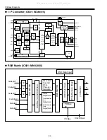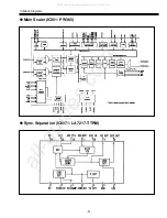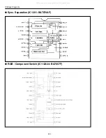
-19-
■
Setting the fixed data
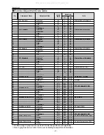
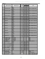
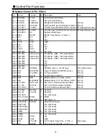
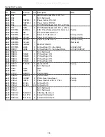
(1) Receive the good quality signal.
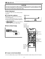
(2) Enter the Service Mode
(3) Confirm fixed data to be same as data table. If it is different, change to
correct data.
(4) Return to the Normal Mode
This adjustment is controlled by the CPU (IC801) thorough the IIC Data Bus Line in the chassis, and those
adjustment data are memorized into the memory IC (IC808). Therefore, SUB CPU Board or the memory
IC (IC808) is replaced, data of those will be disappeared. Readjustment should be made. Initial data is
provided in the CPU ROM ,when memory IC (IC808) is replaced with new one, CPU ROM data is loaded
into the memory. (Data list will be shown in previous 2 pages.) Initial data is provided to operating the
monitor basically. For operating the monitor quality performance, further adjustment required following
chassis electrical adjustment.
Adjustment
■
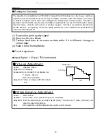
Y-Level Adjustment
Pattern : Color Bar Pattern
Equipment : Oscilloscope
Connection: S-Terminal(K1912) of Monitor Out
Y– Signal – Ground
Note: 75
Ω
Terminated
Adjustment: To be 1
±
0.1Vp-p by VR7001 in Main
Unit.
1
±
0.1Vp–p
White100%
(H)
■
Circuit Adjustment
■
White Balance Adjustment
Pattern : White Pattern
Condition : Screen Size : FULL, Picture Image Level : NATURAL
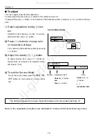
Adjustment : Enter the service mode, select item No. 69 [ Red ], 70 [ Green ] or 71 [ Blue ] (Cont AV), and
adjust a proper white balance.
Note
: After adjustment, confirm white balance again by normal picture.
●
Input Signal : 1.0Vp-p / 75
Ω
terminated
All manuals and user guides at all-guides.com

