-20-
D-SUB
Main
M/O CVBS
IC1001
AV Switch
IC1123
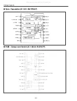
RGB,
Component
SW
IC1124
RGB,
Component
SW
CVBS
Y/C
RGB
Y/C
b
/C
r
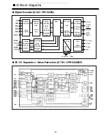
IC401
Digital
Decoder
CVBS
IC7101
3D Y/C Sep.
For NTSC
Y/C
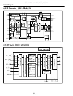
IC501
Interlace/
Progressive
Converter
IC207
A/D Converter
IC601
RGB Matrix
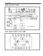
IC301
Main Scaler
IC751
LVDS
Interface
PDP
Panel
Module
RGB
Y/C
b
/C
r
RGB
Y/P
b
/P
r
Y/C
b
/C
r
RGB
Y/P
b
/P
r
RGB
RGB
CVBS3
Y/C3
13
15(Y)
17(C)
CVBS2
Y/C2
7
9(Y)
11(C)
49(Y)
51(C)
CVBS1
Y/C1
1
3(Y)
5(C)
84(Y),83(C)
88
73(Y)
71(C)
75
6(R/Cr)
5(G/Y)
4(B/C
b
)
1(R/Pr/Cr)
3(G/Y)
5(B/P
b
/C
b
)
7(R/Pr)
15(G/Y)
22(B/P
b
)
Sub CPU
PC Analog Input
Jack C
53
56(Y)
58(C)
RGB
Y/P
b
/P
r
R/Pr/Cr4
G/Y4
B/P
b
/C
b
4
R
G
B
7
9
11
1
3
5
21
19
15
R/Pr/Cr
G/Y4
B/P
b
/C
b
21
19
15
R/Pr/Cr
G/Y4
B/P
b
/C
b
AV4
R/Pr/Cr4
G/Y4
B/P
b
/C
b
4
AV3
CVBS3
Y/C3
Jack D
AV2
CVBS2
Y/C2
AV1
CVBS1
Y/C1
Jack A
Monitor
Out
M/O
CVBS
Through
Out
■
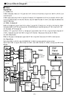
Circuit Block Diagram
■
Video
Signal Flow
(1) CVBS, Y/C
CVBS (Composite Video) or Y/C signal from AV1, AV2 or AV3 terminal is input to AV SW IC (IC1001) and
selected signal.
CVBS signal selected by IC1001 is input to 3 Dimension Y/C Separation IC (IC7101) and input to IC1001 again.
(In case of NTSC Signal) On the other hand it is input to Digital Decoder IC (IC401) and output for Monitor Out
signal (CVBS only).
(2) RGB, Component
RGB or Component signal from AV4 terminal is output for “Through Out” terminal and input to RGB /
Component SW IC (IC1123) and selected to D-SUB RGB signal. Selected signal by IC1123 is input to IC1124.
(3) Decoder, I/P Conversion
CVBS or Y/C signal from IC1001 or Component signal (480i) from IC1124 is input to Digital Decoder IC
(IC401). Component signal from IC401 is input to I/P (interlace / Progressive) Conversion IC (IC501).
(4) A/D Conversion
RGB ( or Progressive Component) signal from IC1124 is input A/D Conversion IC (IC207) and converted.
(5) Panel Drive
Signal from IC501 or IC207 is input to RGB Matrix IC (IC601) and proceeded for picture control.
Signal from IC601 is input to Main Scaler IC (IC301) and LVDS Interface IC (IC751) and input to PDP Panel
Module.
All manuals and user guides at all-guides.com

