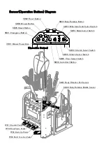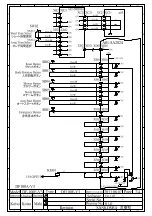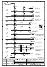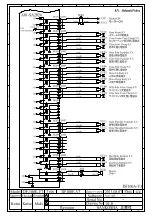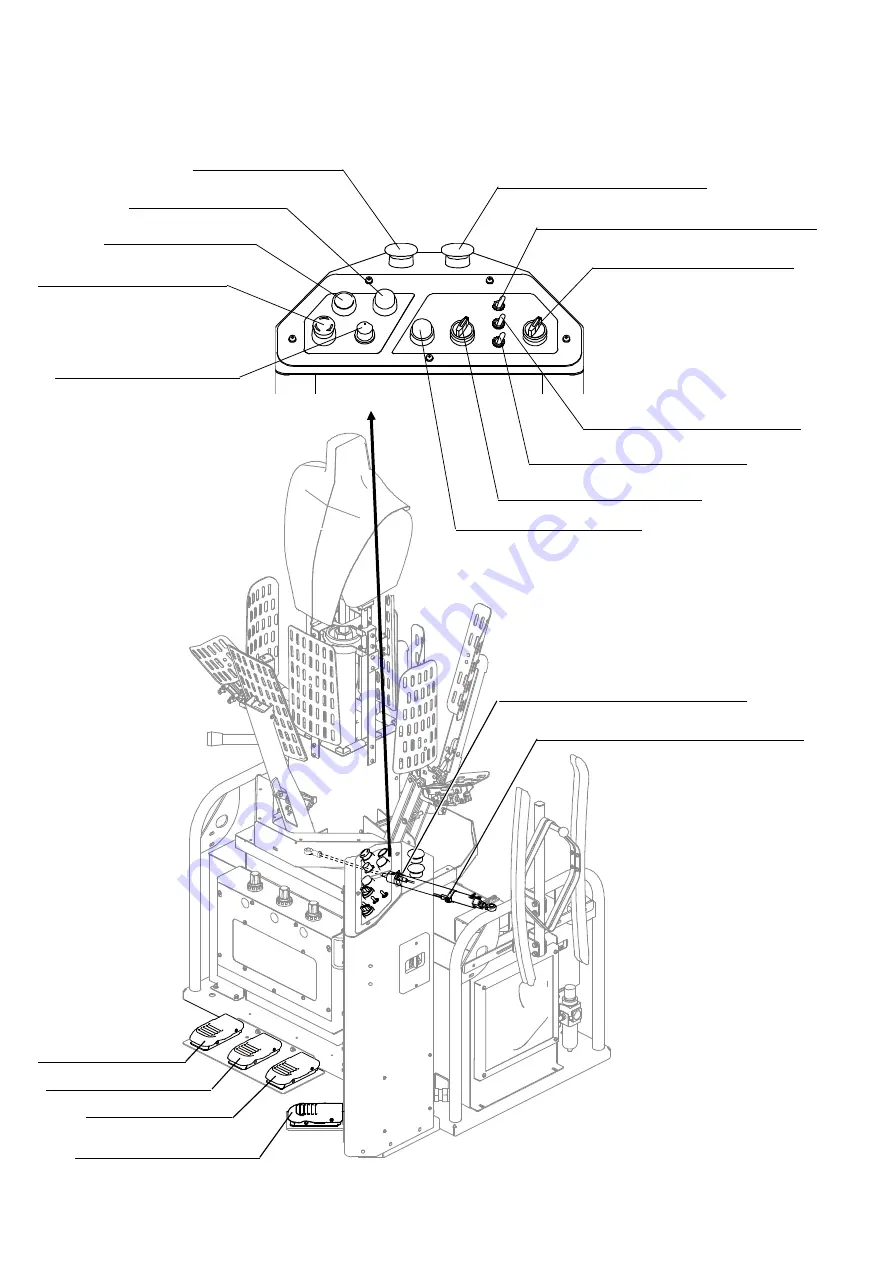
Sensor(Operation Button) Diagram
SB02: Reset Button
(Operation Button)
SW02: Timer Select Switch
SB01: Emergency Button
SB05: Steam Button
SB04: Blower Button
SW03: Wide Side Vents Select Switch
SB03: Body Rotation Button
VR01: Blower Power Dial
SB06: Auto Start Button
SW01: Mode Select Switch
SW05: Stretch Select Switch
SQ01: Body Rotation End Sensor
SQ02: Body Rotation Middle Sensor
FP01: Shoulder Pedal
FP04: Multi Function Pedal
FP03: Body Up Pedal
FP02: Body Down Pedal
SW04: Stretch Select Switch
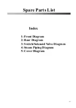
Summary of Contents for DF-100E-V3
Page 40: ...40 ...
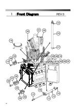
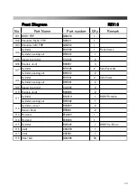
Page 42: ...42 Front Diagram 1 Front Diagram REV 3 ...
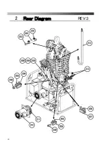
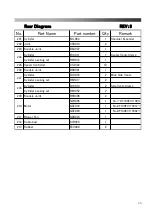
Page 44: ...44 Rear Diagram 2 Rear Diagram REV 3 ...
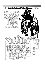
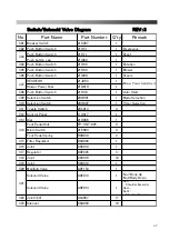
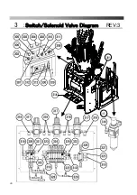
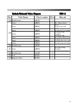
Page 46: ...46 Switch Solenoid Valve Diagram 3 Switch Solenoid Valve Diagram REV 3 315 301 ...
Page 48: ...48 Switch Solenoid Valve Diagram 3 Switch Solenoid Valve Diagram REV 3 315 301 ...
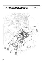
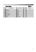
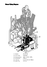
Page 50: ...50 Steam Piping Diagram 4 Steam Piping Diagram REV 3 ...
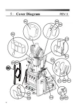
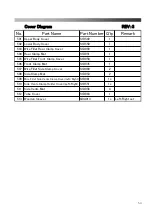
Page 52: ...52 Cover Diagram 5 Cover Diagram REV 3 513 ...
Page 56: ......
Page 57: ......
Page 58: ......
Page 59: ......
Page 61: ......
Page 62: ...DF 100E V3 Rev 6 2019 1 ...

