19
(
6
)
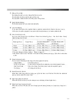
Turn the body to the front side by using the rotation
button (auto), or rotation lever (manual)
(Please see the page 18 Figure-1.)
(
7
)
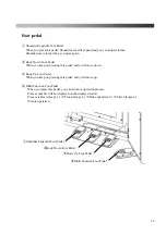
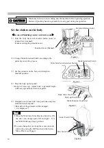
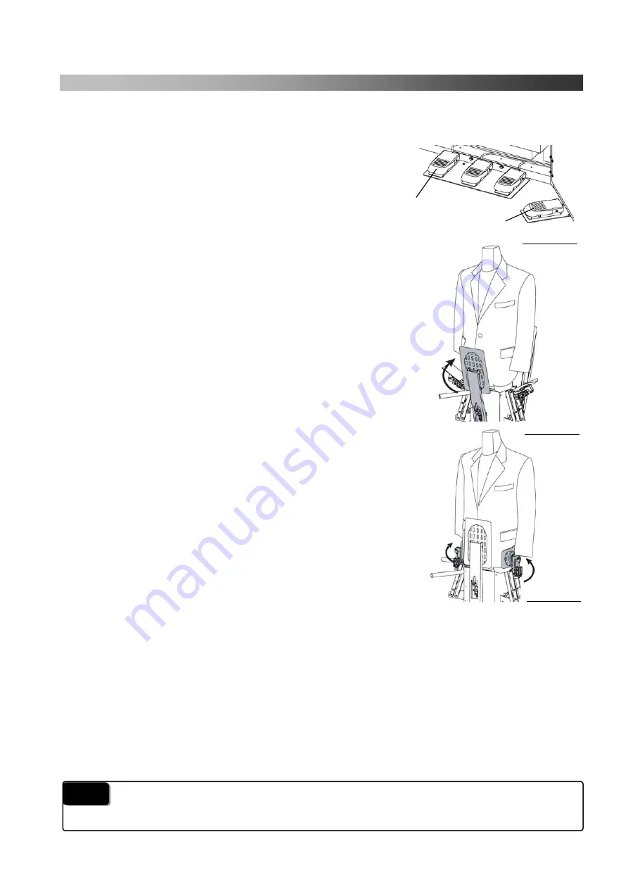
Press the shoulder expander foot pedal.
→
Expander will expand according to garments shoulder line.
Straighten shoulder line if it is needed.
(
8
)
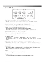
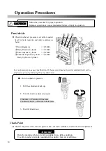
Straighten front placket and press the multi function pedal.
→
Front side of the garments will be clamped.(- 2 - is displayed)
*
If the setting is not correct, push the reset button.
The machine will return to its previous position.
(
9
)
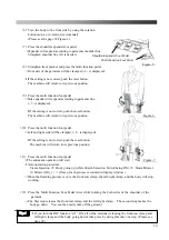
Press the multi function foot pedal.
→
Side expander will expand according to garments line.
(- 3 -is displayed)
*
If the setting is not correct, push the reset button.
The machine will return to its previous position.
(
10
)
Press the multi function foot pedal.
→
Left and right side will be clamped. (- 4 - is displayed)
*
If the setting is not correct, push the reset button.
The machine will return to its previous position.
(
11
)
Press the multi function foot pedal.
→
The automatic operation will start.
*
Auto operation procedure.
Steam Injection
⇒
Body going up (while Stretch Selection Switch being ON)
⇒
Steam/Blower
⇒
Blower (Dry)
・・・
(Time of each process is counted in display window )
→
When the finishing process is over, the front/rear clamp, the left/right clamp, and the body will stop
working.
(
12
)
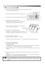
Press the Multi Function Foot Pedal twice while holding the both sides of the shoulder of the
garment.
→
The first step releases the front/rear clamp and the left/right clamp. The second step makes the
body go down. You can then easily take off the garment.
*
If you turn the DIP function “d 5” ON, all of the motions (releasing the front/rear clamp and
left/right clamp and the body going down) take place by using this only one step. (Please see
page 29)
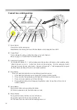
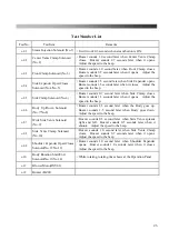
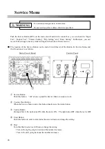
Shoulder Expander Foot Pedal
Multi Function Foot Pedal
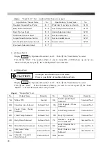
Tips!
Figure-5
Figure-6
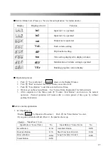
Figure-7
Summary of Contents for DF-100E-V3
Page 40: ...40 ...
Page 42: ...42 Front Diagram 1 Front Diagram REV 3 ...
Page 44: ...44 Rear Diagram 2 Rear Diagram REV 3 ...
Page 46: ...46 Switch Solenoid Valve Diagram 3 Switch Solenoid Valve Diagram REV 3 315 301 ...
Page 48: ...48 Switch Solenoid Valve Diagram 3 Switch Solenoid Valve Diagram REV 3 315 301 ...
Page 50: ...50 Steam Piping Diagram 4 Steam Piping Diagram REV 3 ...
Page 52: ...52 Cover Diagram 5 Cover Diagram REV 3 513 ...
Page 56: ......
Page 57: ......
Page 58: ......
Page 59: ......
Page 61: ......
Page 62: ...DF 100E V3 Rev 6 2019 1 ...

