
31
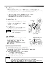
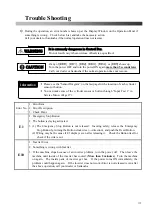
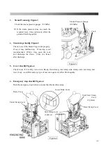
Trouble Shooting
◎
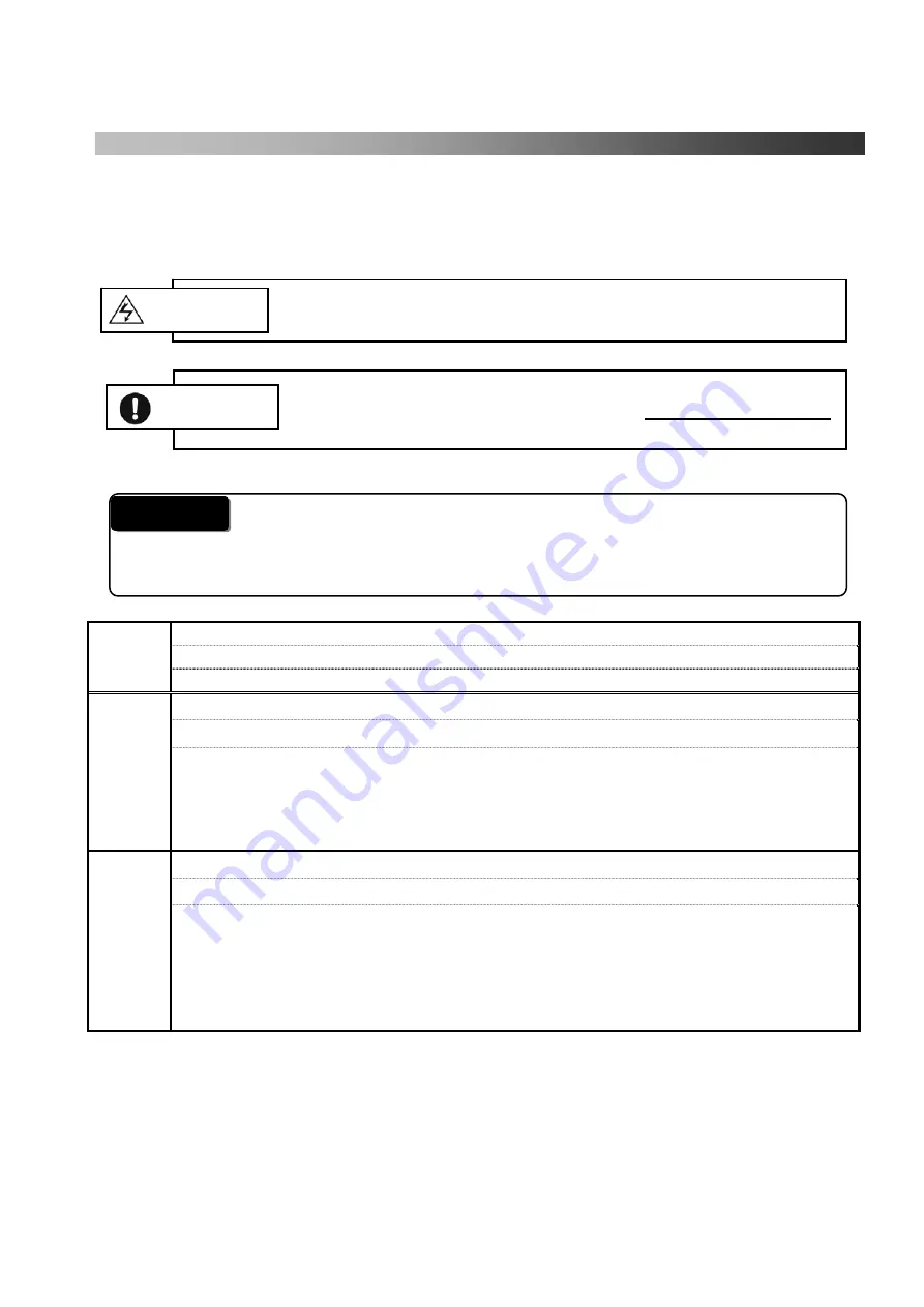
During the operation, an error number shows up at the Display Window on the Operation Panel if
something is wrong. Check below List, and take the necessary action.
Call your dealer or Sankosha if the normal operation does not resume.
If any of [
EEE
]
,
[
EE1
]
,
[
EE2
]
,
[
EE3
]
,
[
EE4
]
,
or [
EE5
] shows up,
Turn the power OFF and turn the power ON again
more than 5 seconds later
.
Call your dealer or Sankosha if the normal operation does not resume.
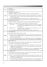
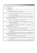
Error No.
1
.
Error Item
2
.
Error Description
3
.
Check Point
E1
1
.
Emergency Stop Button
2
.
The button is staying activated.
3
.
(1) The
Emergency Stop Button is not released. Insuring safety, release the
Emergency
Stop Button by turning the Button clockwise (
→
direction), and push the Reset Button.
(2) Wiring may be the cause if E1 displays even after releasing it. Check the Button itself or
check if the wire is cut.
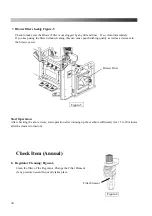
E10
1
.
Inverter Error
2
.
Something is wrong with Inverter
3
.
If the machine stops because of an inverter problem, turn the power off. Then leave the
machine until inside of the inverter has cooled. (
More than 2 minutes)
Turn the machine
on again. The inside parts of inverter get hot. If the power turns ON immediately, the
problem could happen again. If the inverter does not work (Error is not released) even after
the above operation, call your dealer or Sankosha.
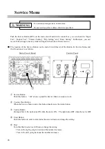
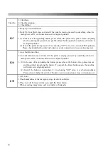
It is extremely dangerous in Control Box.
Do not touch anywhere unless otherwise specified.
WARNING
*
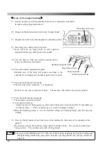
Please see the “Sensor Diagram” on the last page for the location of each cylinder
sensor or button.
*
You can make sure of the cylinder sensor or button through “Input Test 1” in
Service Menu.
(Page 27)
Information
CAUTION
Summary of Contents for DF-100E-V3
Page 40: ...40 ...
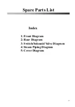
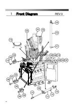
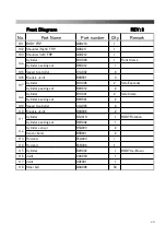
Page 42: ...42 Front Diagram 1 Front Diagram REV 3 ...
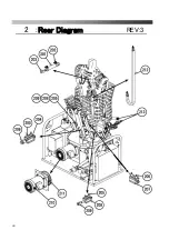
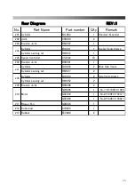
Page 44: ...44 Rear Diagram 2 Rear Diagram REV 3 ...
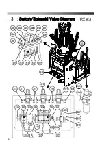
Page 46: ...46 Switch Solenoid Valve Diagram 3 Switch Solenoid Valve Diagram REV 3 315 301 ...
Page 48: ...48 Switch Solenoid Valve Diagram 3 Switch Solenoid Valve Diagram REV 3 315 301 ...
Page 50: ...50 Steam Piping Diagram 4 Steam Piping Diagram REV 3 ...
Page 52: ...52 Cover Diagram 5 Cover Diagram REV 3 513 ...
Page 56: ......
Page 57: ......
Page 58: ......
Page 59: ......
Page 61: ......
Page 62: ...DF 100E V3 Rev 6 2019 1 ...


