CP3005 – User Guide Rev. 1.8
// 77
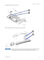
Figure 26: CP-RIO3-04 8HP Rear Transition Module Layout
9.5.
Module Interfaces
9.5.1.
USB Interfaces
The CP-RIO3-04 rear transition module provides two standard, type A, USB 2.0 connectors, J11 and J12, on the front
panel.
9.5.2.
VGA Interface
The CP-RIO3-04 provides one standard VGA interface for connection to a monitor. The VGA interface is implemented
as a standard VGA connector (J7) on the front panel.
9.5.3.
Gigabit Ethernet Interface
The CP-RIO3-04 provides two Gigabit Ethernet interfaces realized as RJ-45 connectors without LEDs. The status
information of these both interfaces are indicated on the front Ethernet connector. The interface provides automatic
detection and switching between 10Base-T, 100Base-TX and 1000Base-T data transmission (Auto-Negotiation).
Auto-wire switching for crossed cables is also supported (Auto-MDI/X).
9.5.4.
COM Interface
The CP-RIO3-04 rear transition module provides two identical COM ports for connection to RS-232 devices. On the
8HP version, the onboard 10-pin serial connectors J2 and J3 are routed to the 9-pin D-Sub COM connectors J2a and J3a
located on the front panel. On the 4HP version, the COM signals are available only on the onboard 10-pin serial port
connectors J2 and J3.
The following table provides pinout information for the onboard serial port connectors J2 and J3. Refer to the module
layout for connector and pin locations.


