


CP3005 – User Guide Rev. 1.8
// 29
3.6.
Battery
The CP3005 is provided with an UL-recognized BR2032, 3.0 V, “coin cell” lithium battery for the RTC. When a battery is
installed, refer to the operational specifications of the battery as this determines the operating and storage
temperature of the CP3005.
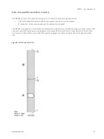
The battery is mounted on a battery module (MMBAT02) on the CP3005 board or on the
MMEXT05 extension module – but never on both devices.
For modules of the extended series (85°C), sufficient air flow must be ensured in the
cooling system. Before final commissioning, test operation with temperature
measurement on the battery is recommended.
3.7.
Flash Memory
The CP3005 provides flash interfaces for the uEFI BIOS and a M.2 Flash module.
3.7.1.
SPI Boot Flash for uEFI BIOS
The CP3005 provides two 2x 16 MB SPI boot flashes for two separate uEFI BIOS images, a standard SPI boot flash and
a recovery SPI boot flash. The fail-over mechanism for the uEFI BIOS recovery can be controlled via the DIP switch
SW1, switch 2.
The uEFI BIOS code and settings are stored in the SPI boot flashes. Changes made to the uEFI
BIOS settings are available only in the currently selected SPI boot flash. Thus, switching over
to the other SPI boot flash may result in operation with different uEFI BIOS code and
settings.
3.7.2.
M.2 Flash Module
The M.2 connector (Type 2242) can be used for a SSD flash module for operating system and data.
3.8.
Trusted Platform Module
The CP3005 supports the Trusted Platform Module (TPM) 2.0. TPM 2.0 is a security chip specifically designed to
provide enhanced hardware- and software-based data and system security. It is based on Infineon's SLB9670.
Infineon’s Trusted Platform Module (TPM) SLB9670 is featuring a fully TCG TPM 1.2/2.0 standard compliant module
with a SPI interface. TPMs are widely used as a root of trust for platform integrity, remote attestation and
cryptographic services.