


8 S&C Instruction Sheet 661-500
Components
Table 4. Component Descriptions
Component or Label
Type
Description
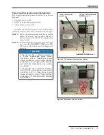
CHARGER ON/OFF
Switch
The charger will be powered from any of the three sources (three-phase, 120 Vac, or battery) when
this switch is turned on . Charging power is exported from the charger only when the battery is
connected .
Simulated Loss of
Primary Feeder
(three-phase power
switch)
Switch
Turns on/off the three-phase voltage sensors to the charger
120 Vac
Switch
Turns on/off the 120-V single-phase ac source to the charger
COMM PORT
DB9 connection
port
Using a USB-to-DB9 serial cable, this port is used to connect a computer to the charger in order to
use the GUI application software
Upper-right green
connector
①
Wire connection
terminals
This is the J2 connector . Used to connect output wires
Lower-right green
connector
①
Wire connection
terminals
This is the J3 connector . Used to connect power wires
Upper-left green
connector
①
Wire connection
terminals
This is the J4 connector . Used to connect control wires
J2 connector pinout
label
Drawing label
Shows the pin locations to connect the output wires
J3 connector pinout
label
Drawing label
Shows the pin locations to connect the power wires
J4 connector pinout
label
Drawing label
Shows the pin locations to connect the control wires
UP
②
Pushbutton
Used to increment digits on the LCD screen . The digit displayed after the maximum will roll back to
the minimum digit
DOWN
②
Pushbutton
Push and hold: Used to change programming modes on the LCD screen
Push: Used to shift to the next digit(s) on the LCD screen
RESET
②
Pushbutton
Used to reset the charger when any of these occurs:
• The battery is bad
• The battery has open cells
• The battery has been removed
BAT TEST
②
Pushbutton
Used to test the battery
BATTERY TESTING
LED
Indicator turns on during battery testing
UNDER VOLTAGE
LED
Turns on when the battery voltage is lower than 21 Volts
OVER VOLTAGE
LED
Turns on when the battery voltage is higher than 34 Volts
AC NOT PRESENT
LED
Turns on when the charger is powered by the battery only
Screen
LCD screen
Used to show menus and status of the battery charger
①
Refer to Appendix B for wire connector pin location details .
②
S&C recommends using the GUI application software to operate and
configure the charger . See pages 11 to 16 . For manual operation, refer
to Appendix A .