S&C TA-3370 Instruction Sheet Download Page 14

14    S&C Instruction Sheet 661-500

Operation

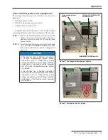
Figure 10. Fields on the Settings screen that are configurable.
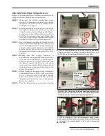
STEP  4.  

Connect the desired battery. Click on the 

Alarm 

Reset

 button to enable the battery to reconnect 

to the charger. When the button is clicked, a 
message will pop up, “Do you want to override 
the BAT Records?” See Figure 9.

STEP  5.  

Click on the 

Yes

 button if battery test results 

must be overwritten. This is recommended if 
the battery was replaced so records from the old 
battery are not displayed for a newly installed 
battery.

STEP  6.  

Click on the 

No

 button if battery test results 

must be stored. This is recommended if the 
battery was just unplugged for maintenance.
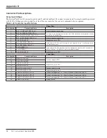
Settings Tab

In the 

Settings

 tab, the user can configure the charger with 

the fields shown in Figure 10. Each setting must have the 
box to the left of the setting checked in order to be saved. 
Table 6 shows the descriptions of the fields shown on the 

Settings

 screen.

Table 6. Field Descriptions for the Settings Tab

Field

Description

Battery Charger Current

The user can set the battery charger 

current . The current range is from 0 .000 

to  .500 amperes . A readback of this 

value is displayed on the 

Battery Status 

screen under the 

User Set Max Current 

field .

Date/Time

The user can configure the date and 

time . By placing the cursor on the exact 

parameter, the user can click on the 

up and down arrows to increment or 

decrement the values respectively .

The date and time can also be entered 

by means of the keyboard numbers and 

traversing left and right by using the 

keyboard arrows .

Date is in the form of MM/DD/YYYY and 

time is in the form of HH:MM:SS  

(24-hour format) .

Remove battery from 

charger under BAD 

condition or less than 

17 .5 V

The charger will disconnect the battery 

from the charger under the 

Battery Bad 

condition or if battery voltage is less 

than 17 .5 V .

Select the 

Yes option if the battery 

should be disconnected .

Select the 

No option if the battery 

should not be disconnected .

A readback of this selection is displayed 

on the 

Battery Status

 screen under the 

Bad Battery or Under 17.5V Action 

field .

Save

This button allows the user to save the 

changes made to the checked/selected 

configurable fields .

Update Setting

This status bar shows the % completion 

of the saving process when the 

Save 

button is used .

 Default answer is the 

Yes option (recommended) .

Figure 9. The battery test results override pop up window.

Summary of Contents for TA-3370

Page 1: ...tings and Standards 6 Components Overview 7 Wiring Interface 9 LCD Screen 10 Operation Accessing the GUI Application Software 11 Navigating the GUI Application Software 12 Power Switch Operation and C...

Page 2: ...whenever Three Phase Battery Charger is to be used Retain this instruction sheet in a location where you can easily retrieve and refer to this publication Proper Application WARNING The equipment in...

Page 3: ...precautions are not followed NOTICE NOTICE identifies important procedures or requirements that can result in product or property damage if instructions are not followed Following Safety Instructions...

Page 4: ...eing performed inside the enclosure Mini Rupter Switches have switch operating shaft access covers located on the sides of the pad mounted gear enclosure They must be closed and padlocked at all times...

Page 5: ...and tested for voltage install suitable grounding cables in all compartments before touching any device to be inspected replaced serviced or repaired in the high voltage compartments 13 SWITCH POSITIO...

Page 6: ...85 C 40 F to 185 F Relative humidity 5 to 95 at 60 C 140 F non condensing Regulatory Compliance The Three Phase Battery Charger complies to the following standards Emissions Testing IEC 60255 26 2013...

Page 7: ...raphical user interface GUI computer application software to monitor the gear Table 4 on page 8 provides the description of the components J4 connector pinout label J2 connector pinout label J3 connec...

Page 8: ...hows the pin locations to connect the output wires J3 connector pinout label Drawing label Shows the pin locations to connect the power wires J4 connector pinout label Drawing label Shows the pin loca...

Page 9: ...flathead screwdriver unscrew the pin location needed to wire See Figure 3 STEP 2 When the pin screw is loosened place the bare part of the wire in the square slot under the loosened screw and tighten...

Page 10: ...the LCD screen are also cleared if the charger is turned off and then turned back on This information will automatically scroll on the LCD screen every three seconds Display on the screen when the cha...

Page 11: ...harger and the USB end to the user s computer STEP 2 Run the BatteryCharger exe file from the computer to launch the GUI application NOTICE The GUI application software BatteryCharger exe file can be...

Page 12: ...tab is the default screen when the user logs in and is used for updating the charger firmware See Figure 7 Table 5 defines the fields and buttons in the Firmware Upload screen Table 5 Firmware Upload...

Page 13: ...to be refreshed to capture present data Click on the Battery Status tab to refresh The two buttons the user can use are Convert to C This button enables the user to convert the temperature seen on the...

Page 14: ...000 to 500 amperes A readback of this value is displayed on the Battery Status screen under the User Set Max Current field Date Time The user can configure the date and time By placing the cursor on t...

Page 15: ...ty and can be started remotely with the GUI application Battery Test command as shown in Figure 11 by the Battery Test Start input relay through the J2 connector or by the BAT TEST pushbutton on the c...

Page 16: ...n the Test History button This will enable the user to see the subtab report NOTICE If the data does not appear click on the Test History button again to refresh the data STEP 3 If desired the user ca...

Page 17: ...is turned on turn on the CHARGER POWER switch The LCD screen will turn on and the charger will power on NOTICE If the charger has a battery connection a 120 Vac single phase power source connection an...

Page 18: ...minate the wires STEP 3 Connect the two pin connector See Figure 17 Before turning on the charger use a voltmeter to confirm the voltage at the J2 connector Voltage across pin 1 battery positive and p...

Page 19: ...rs on the GUI application software STEP 4 To place a new battery or to rewire the existing battery to the charger follow Steps 2 through 4 of the previous section on page 18 STEP 5 Using the Battery S...

Page 20: ...wire to pin 1 and battery negative wire to pin 4 of the J2 connector See the J2 connector pinout label on the charger faceplate for exact pin locations to terminate the wires Now connect the two pin c...

Page 21: ...head screwdriver to secure the 24 Vdc battery to the charger by connecting the battery positive lead to pin 1 and the battery negative lead to pin 4 on the J2 connector Now connect the two pin connect...

Page 22: ...s no 120 Vac single phase power source connected to the charger the charger will be powered by the three phase power source If there is a 120 Vac single phase power source connected to the charger the...

Page 23: ...t If these actions do not resolve the issue contact S C Electric Company BAT LOW appears on the LCD screen or in the GUI application Battery voltage is less than 22 Vdc during a battery test Troublesh...

Page 24: ...urrent date and time via the LCD screen NOTICE S C recommends using the Settings tab in the GUI application software to configure the battery charger See page 14 for configuration instructions Complet...

Page 25: ...CE The UP button increases the value of the digit by 1 At the maximum value 12 for month the next push rolls over to the minimum value 1 for month Certain digit positions within the configurable value...

Page 26: ...STEP 3 To select another position push the DOWN pushbutton which will move the flashing position to the right Push it again to go to another position to change its value STEP 4 When the desired value...

Page 27: ...Battery status Date Time Temperature VL voltage under load BZ battery impedance NOTICE The battery test results on the LCD screen will be overwritten by the results of subsequent battery tests The bat...

Page 28: ...o RTU 6 BAT TEST START INPUT Apply external 24 Vdc positive to pin 6 and negative to pin 7 for 3 seconds to start the battery test 7 BAT TEST START INPUT 8 ALARM RESET Apply external 24 Vdc positive t...

Page 29: ...ON 1 Relay dry contacts for Battery Under Voltage condition indicator The relay will turn on when the battery voltage is below 23 V when an ac source is present and 22 V when an ac source is not prese...

Page 30: ...t for 10 seconds Using a voltmeter measure the voltage Vac at the J2 connector and record the measurements in the Table 13 Table 13 Analog Output Voltage Analog Output Voltage Phase 1 J2 20 to J2 17 P...

Page 31: ...S C Instruction Sheet 661 500 31 Appendix D Drawings Figure 29 Interconnect diagram...

Page 32: ...MENTAL TO S C 0 000 SCHEMATIC F P 3 PHASE P S BAT CHARGER C 08 13 2018 TP BAT CHARGER 006 003091 01 S C ELECTRIC COMPANY E x c e l l e n c e T h r o u g h I n n o v a t i o n PROPRIETARY STATEMENT THI...

Page 33: ...NG THE EXPRESS WRITTEN PERMISSION OF DESCRIPTION DRAWING NO SHEET O DATE DRAWN BY SIZE REVISION ASSEMBLY PRODUCT S C THIS DOCUMENT IS PROVIDED UNDER THE EXPRESS CONDITION THAT IT WILL BE HELD IN CONFI...

Reviews: