


28 S&C Instruction Sheet 661-500
Appendix B
Connector Pin Descriptions
Relay Input Voltage
The Battery Test Start (J2 connector, pins 6 and 7) and Alarm Reset (J2 connector, pins 8 and 9) contacts must be powered
with 24 Vdc. Voltage must be applied for at least three seconds for the contact command to be recognized.
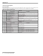
Table 8. J2 Connector Input Definitions
Upper Row
Pin Number
Connection Name
Description
1
BAT + (FIRST BATTERY 12 V+)
Battery (positive) connection
2
BAT Tie (FIRST BATTERY 12 V-)
Pin 2 and 3 are tied together to allow two 12-Vdc batteries to be placed in series
to create a 24-Vdc battery .
3
BAT Tie (SECOND BATTERY 12 V+)
4
BAT - (SECOND BATTERY 12 V-)
Battery (negative) connection
5
(-)24 VDC OUTPUT
Negative supply to RTU
6
BAT TEST START INPUT (+)
Apply external 24 Vdc (positive to pin 6 and negative to pin 7) for 3 seconds to
start the battery test .
7
BAT TEST START INPUT (-)
8
ALARM RESET (+)
Apply external 24 Vdc(positive to pin 8 and negative to pin 9) for 3 seconds to
reset all alarms . This reset will not cycle power to loads .
9
ALARM RESET (-)
10
(-24) VDC OUTPUT
Negative supply to RTU
Lower Row
Pin Number
Connection Name
Description
11
(+24) VDC OUTPUT
Positive supply to RTU
12
(+24) VDC OUTPUT
13
(-24) VDC OUTPUT
Negative supply to RTU
14
(-24) VDC OUTPUT
15
RADIO POWER +12 VDC
Positive supply to radio
16
RADIO POWER -12 VDC
Negative supply to radio
17
PHASE 3 ANALOG OUTPUT
Phase 3 analog output . 1 V = 32 mA at Phase 3 input current (J3 .4)
18
PHASE 2 ANALOG OUTPUT
Phase 2 analog output . 1 V = 32 mA at Phase 2 input current (J3 .6)
19
PHASE 1 ANALOG OUTPUT
Phase 1 analog output . 1 V = 32 mA at Phase 1 input current (J3 .2)
20
ANALOG GROUND
Analog ground