


18 S&C Instruction Sheet 661-500
Operation
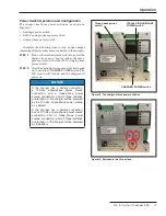
Figure 19. The LCD will turn on when the CHARGER POWER
switch is in the On position if a battery is connected.
Connecting and Powering On the Charger
with a 24-Volt Battery
Complete the following steps to connect and power on the
charger with a 24-Vdc battery:
STEP 1.
Make sure the 120-Vac single-phase power
switch, the three-phase power switch, and the
charger power switch are in the
Off
position.
See Figure 16 on page 17.
STEP 2.
Making sure the two-pin connector is
disconnected, use a small fl athead screwdriver
to confi rm the 24-Vdc battery wires to the
charger are connected. The battery positive
wire should be connected to pin 1 and the
battery negative wire should be connected to
pin 4 of the J2 connector. See the J2 connector
pinout label on the charger faceplate for exact
pin locations to terminate the wires.
STEP 3.
Connect the two-pin connector. See Figure 17.
Before turning on the charger, use a voltmeter
to confi rm the voltage at the J2 connector.
Voltage across pin 1 (battery positive) and pin 4
(battery negative) should be between 20 Vdc and
26 Vdc (depending on the battery state of
charge). See Figure 18.
STEP 4.
Turn the CHARGER POWER switch to the
On
position. The charger will turn on, and the LCD
screen will display the charger and battery
status. See Figure 19.
NOTICE
With the charger power switch on, the
battery will power the charger if no 120-Vac
single-phase power source or three-phase
power source is supplied to the charger,
regardless of the 120-Vac single-phase or
three-phase power switch positions .
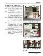
Figure 17. Battery wires connected to the J2 connector. The J2
connector pinout label is used as a reference for battery wire
connection locations.
Sample battery
Two-pin
connector
Battery wire
connections
J2 connector
pinout label
Figure 18. Locations to test the battery connections using a
voltmeter.
Battery wires
Voltmeter leads