


S&C Instruction Sheet 661-500 21
Operation
with S&C Three-Phase Voltage Sensors
Complete the following steps to connect and power on the
charger with S&C three-phase voltage sensors:
STEP 1.
Make sure the 120-Vac single-phase power
switch, the three-phase power switch, and the
charger power switch are in the
Off
position.
See Figure 16 on page 17.
STEP 2.
Using a small fl athead screwdriver, connect the
three-phase voltage sensor power source wires
to the J3 connector by connecting the Phase 1
ground wire to pin 1, Phase 1 line wire (hot) to
pin 2, Phase 2 ground wire to pin 5, Phase 2 line
wire (hot) to pin 6, Phase 3 ground wire to pin 3
and Phase 3 line (hot) to pin 4. See Figure 24.
STEP 3.
Use a voltmeter to confi rm the voltage at the J3
connector before turning the three-phase power
switch to the
On
position. Voltage between pin 1
and pin 2, pin 3 to pin 4, and pin 5 to pin 6 should
be in between 5 Vac and 6.5 Vac (depending on
the system line voltage). See Figures 25(a), 25(b),
and 25(c).
STEP 4.
Making sure the two-pin connector is
disconnected, use a small fl athead screwdriver
to secure the 24-Vdc battery to the charger by
connecting the battery positive lead to pin 1 and
the battery negative lead to pin 4 on the J2
connector. Now, connect the two-pin connector
so the battery is connected to the charger. See
Figure 17 on page 18.
STEP 5.
Before turning on the charger, use a voltmeter to
confi rm the voltage at the J2 connector. Voltage
at pin 1 (battery positive) and pin 4 (battery
negative) should be between 20 Vdc and 26 Vdc
(depending on the battery state of charge). See
Figure 18 on page 18.
STEP 6.
Turn the three-phase power switch to the
On
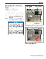
Figure 23. The CHARGER and 120-Vac single-phase power
switches are in the On position. The LCD screen will turn on if
the 120-Vac power source or the battery is connected.
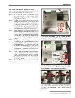
Figure 24. The three-phase voltage sensor power source wires
connected to the J3 connector. The J3 connector pinout label
is used as a reference for wire connection locations.
Figure 25. Locations to test the three-phase voltage sensor
power source wire connections using a voltmeter: (a) measuring
pin 1 to pin 2, (b) measuring pin 3 to pin 4, and (c) measuring
pin 5 to pin 6.
(b) Voltmeter
leads
Three-phase
voltage
sensor power
source wires
J3 connector
pinout label
(a) Voltmeter
leads
(c) Voltmeter
leads