26 S&C Instruction Sheet 1072-530
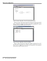
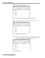
Figure 44. Network Configuration of Serial Pass-Through Mode Settings.
Figure 44 shows the Pass-through settings. The settings in this dialog correspond to
those in the SpeedNet Client Tool described in the “Serial Pass-through Mode” section
on page 43. There is no
Apply
button on this window because application to a radio is
deferred until uploaded using the SpeedNet Client tool.
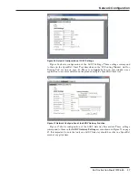
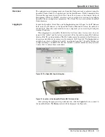
Figure 45. Network Configuration of Serial Port’s Settings.
Figure 45 shows the Serial Port settings. These settings correspond to those in the
SpeedNet Client Tool described in the “Interfaces Window, Serial Port Tab” section on
page 42. There is no
Apply
button on this window because application to a radio is deferred
until uploaded using the SpeedNet Client tool.
Network Confi guration


