background image


15

1. 

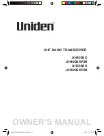
Display Device


 Power   

Power ON/OFF


 Diplay Menu & move to sub menu 

Select, Input, Excution   

Select  Mark/Track/Erase/Watch

/Sunken Vessel, Banks 


Direction Button


•Move a chart to 4 ways and 

cursor.


•Move a menu cursor, etc.


 Zoom IN 

•Inlarge the display


•Input numbers


Cursor 

•Display a cursor in display


 Zoom Out 

•  Enlarge the display 


•  Input numbers


Switch Button 


N/S, W/E, +/- mutual Switch 

Waypoint Jump & Reverse Navigation Button 

.Fish Finder frequency select Low/High 

Soft Key : Mark color, Track color, Erase port,   

Sunken Vessel, Fishing Banks, Waypoint, Calendar 

 C-User, C-Map card Slot 

C-User card slot (Left) 

: User Data Load/BackUp 

C-Map card slot (Right) 

: Load C-Map chart 

SD card slot   

Summary of Contents for Navis 3800

Page 1: ...vanced Navigation device since ever developed However a navigation officer of ability should not make a decision by information from this device only which might be occurred damages in people s life a...

Page 2: ...y 1 Display Device 15 2 Remote Controller Button 16 3 Power ON OFF 17 4 Menu 18 5 Display mode 19 Chapter 4 Operating Instruction 1 Data 26 1 1 Track Data 26 1 1 1 Track Set 26 1 1 2 Track Clear 27 1...

Page 3: ...Disk Format 45 1 7 Seabed Symbol 46 1 8 Program Update 47 2 Set Up 47 2 1 Navigation Set 47 2 1 1 Waypoint Navigation Set 47 2 1 2 Route Navigation Set 49 2 1 3 Anchor Set 51 2 1 4 EXIT WPT RTE ANCHOR...

Page 4: ...Noise Erase 75 4 3 Color Erase 76 4 4 Tx Power Set 76 4 5 PULSE WIDTH SET 77 4 6 COLOR PATTERN SET 77 4 7 A SCOPE SET 78 4 8 ETC SET 78 5 Weather Fax 79 5 1 BROADCAST SET 80 5 2 PRINTING SET 80 5 3 R...

Page 5: ...89 6 8 MEDIA OFF 90 6 9 ETC SET 90 Chapter 5 System Maintenance Diagnosis 1 System Maintenance and Repair 92 2 Diagnosis 92 Appendix Appendix 1 Weather Fax receiving frequencies and time table 94 Appe...

Page 6: ...7 This chapter provides an overview of the GLOBAL POSITIONING SYSTEM GPS 1 1 1 1 GPS PLOTTER...

Page 7: ...uire the position Once the GPS Plotter has received an accurate fix from the satellites ship s position bearing time speed and other operations can be calculated GPS Global Positioning System has two...

Page 8: ...9 This chapter provides Features of NAVIS GPS Plotter GPS Antenna Receiver DGPS Antenna Beacon Receiver Main Unit Features Functions Standard Components 2 2 2 2 FEATURES...

Page 9: ...eiving Architecture 16 channel Multiple Tracking Receiving Channel 16 channel Receiving Code C A code 1 023 MHz chip rate Tracking Capacity 12 simultaneous satellite vehicles Receiving Sensitivity Les...

Page 10: ...ndition Temp Antenna 40 70 Main Unit 15 55 Humidity 95 30 C 60 C Positioning Tracking Speed Velocity 1000Knots 514 m s Acceleration 4g Signal Correction Tracking Full Auto Tracking Micro Computer Accu...

Page 11: ...Line Drawing Mark 999 points Waypoint Route Memory 10 000 points 20 routes 1 route 20 points Navigation 2 Auxiliary Memory Unit Coast Line TRACK Event Waypoint User s Line to be saved Disk save C User...

Page 12: ...EA 2 GPS Antenna SAN 60 1EA 3 Antenna Cable RG 58C U 10 20m 4 DC Cable SQ 0 75 X3P 3m 5 Spare Fuse 7A 1EA 6 Spare Fuse 3A 1EA 7A 1EA 2EA 7 Install Material 1LOT 8 Transducer 50KHz or 200KHz 50 200Khz...

Page 13: ...14 This chapter provides Device Display about GPS Plotter Display Device Remote Controller Power ON OFF Menu Plotter Display 3 3 3 3 Device Display...

Page 14: ...e the display Input numbers Cursor Display a cursor in display Zoom Out Enlarge the display Input numbers Switch Button N S W E mutual Switch Waypoint Jump Reverse Navigation Button Fish Finder freque...

Page 15: ...sh Finder ENT Select Menu Input Data Insert Event mark Erase 8 Direction Button Moving Chart Cursor Menu CTR Move ownship to the center Move Cursor position to the center Select figures to input ESC R...

Page 16: ...17 3 Power ON OFF Power ON Press Power OFF Press and hold approximately 2 sec...

Page 17: ...ETC SET 3 SYSTEM 1 SATELLIE INFO 2 SCREEN PRINT 3 KEYBOARD TEST 4 SYSTEM SET 5 SYSTEM INFO 4 FISH 1 SCREEN SPEED 2 NOISE ERASE 3 COLOR ERASE 4 TX POWER SET 5 PULSE WIDTH 6 COLOR PATTERN 7 A SCOPE SET...

Page 18: ...le display mode by Display mode change at Plotter Display Only Display mode change at Plotter Fishfinder Display Plotter Navigation Fishfinder Plotter Navigation Plotter Fishfind Always power OFF when...

Page 19: ...20 GPS Plotter Display C MAP Plotter Display 31...

Page 20: ...13 Latitude of Cursor Latitude of current cursor position 14 Longitude of Cursor Longitude of current cursor position 15 Distance to Cursor Distance between current position and cursor 16 Bearing Bear...

Page 21: ...Mode in Plotter Display The brightness and transparency can be adjusted when button is pushed in plotter or plotter fish finder screen Also button is pushed the day night display mode can be switched...

Page 22: ...23 Navigation Display In Navigation Display Press You can see Ownship s position Speed Bearing in full screen which is helpful for your sailing...

Page 23: ...24 Fish finder Combo Display Fish finder Display...

Page 24: ...25 This chapter provides Operating Instruction in NAVIS series DATA SET SYSTEM FISH Fishfinder NAVIS 3800F Fax Media Option 4 4 4 4 Operating Instruction...

Page 25: ...put to set time 4 DISTANCE 2 SELECT Input to set distance 5 COLOR Select color of TRACK line 6 SHARP Select color of TRACK line 7 T MARK Select ON OFF of TRACK To select color of TRACK line Press sele...
Page 26: ...rm Select YES NO Press Select 3 TRACK ERASE then display Track Clear menu 1 1 3 Track CALC Use this function to calculate the Vessel s TRACK 1 DATA 1 TRACK DATA 3 CALC 1 DATA 1 TRACK DATA 2 CLEAR Ref...

Page 27: ...ut 4 digits of file name by using Direction button button or number button and then Press button Numbers can be possible only in f ile name After select things to be saved and then press button Intern...

Page 28: ...Storage Select 1 DATA 1 TRACK DATA 5 LOAD Ref In using a new C User card you must use it after making a initial disc once Refer to 1 6 DISK FORMAT How to save call Track by transmitting data The funct...

Page 29: ...a file name and then press button in order to show Do you want to erase and select YES NO If select Internal ROM following two menus are displayed Memory Clear Erase TRACK on the screen File Name Era...

Page 30: ...ARK To select Color Press Select 1 M COLOR and Push which is the other pass 1 2 2 Mark Append It is a function to append MARK at location of Ownship or certain Latitude Longitude 1 DATA 2 MARK DATA 2...

Page 31: ...he screen If you use out of 10 000MARK It is shown MARK out message in the screen In order to use MARK at any time You may control Q ty of MARK less than 10 000 points 1 2 3 Mark Clear 1 2 2 Function...

Page 32: ...value by direction button number button convert button then press button 1 2 4 Mark Save 1 2 2 Mark Append is saved to saving tool as a file Insert things to be saved Possible to omit when using Inter...

Page 33: ...5 Mark Load 1 2 4 Display a mark in a Plotter screen after calling a saved file from a storage tool Insert save device to load saved file Possible to omit when using Internal ROM COM PORT Select a sto...

Page 34: ...a file name and then press button in order to show Do you want to erase and select YES NO If select Internal ROM following two menus are displayed Memory Clear Clear MARK marked into a Plotter screen...

Page 35: ...s Line Drawing in advance After select ON OFF button by using a direction button and press button 1 3 2 Coastal Line Drawing Displayed a coastal line by a user and it can register Line drawing Mud MA...

Page 36: ...e erased by using a direction button and press button The line color or Mark color is changed after press button 1 3 3 Coastal Line Save 1 3 2 Coastal data is saved into a storage tool in a coastal dr...

Page 37: ...lotter screen is deleted when call the coastal line file at that time 1 DATA 3 USER S LINE 4 LOAD Ref In using a new C User card you must use it after making a initial disc once Refer to 1 6 DISK FORM...

Page 38: ...s are displayed Memory Clear Delete a coastal line marked into a Plotter screen File Name Delete a saved coastal line into a file of ROM The file name is marked in saving a file only 1 DATA 3 USER S L...

Page 39: ...N OFF button by using a direction button and press button 1 4 2 Waypoint Edit Function to register a point of an important or frequent navigation in advance and can be possible to register till 999 sc...

Page 40: ...1 4 3 Waypoint Save This function is to save the Lat Long of the waypoint MARK name registered from 1 4 2 Waypoint Edit into an available storage tool as a file 1 DATA 4 WAYPOINT DATA 3 SAVE Ref How...

Page 41: ...tached and saved in the front of the file name auto input and it means a Way Point 1 4 4 Waypoint Load 1 4 3 Display a waypoint in a Plotter screen after calling a saved file from a storage tool 1 DAT...

Page 42: ...nt Erase 1 4 3 Deleted a coastal line file from a storage tool Must be careful to command this erase due to no recover the file 1 DATA 4 WAYPOINT DATA 5 ERASE Once you load waypoint data file Current...

Page 43: ...ted in a plotter screen File Name Erase waypoint saved internal ROM as a file T he file name is marked in saving a file only 1 5 Route Data 1 5 1 Route Edit Function to register waypoint into a naviga...

Page 44: ...led and then press button In case of navigating to jump up a certain of the waypoint in a navigate route move the cursor to the required number and then press button J Jump character is shown in besid...

Page 45: ...unction to see description of abbreviated form and symbol for seabed displayed on the plotter chart 1 DATA 7 SEABED TYPE Once you format disk Existing data would be erased at all CAUTION Ref In case o...

Page 46: ...2 1 1 Waypoint Navigation Set This function is used when the vessel navigates between two waypoints registered in 1 4 2 Waypoint Edit or to the waypoint registered in a current own position 2 SET 1 N...

Page 47: ...creen How to choose Waypoint Navigation shortcut by using button menu In the current position if you want to go to the saved waypoint on the plotter screen press select Waypoint with direction key and...

Page 48: ...button It set up a reverse navigate in showing R character When press button once more it returns to a forward navigate 2 SET 1 NAVIGATION SET 2 ROUTE NAVIGATION Ref Watch Set Up It is an opposite not...

Page 49: ...ellation How to set up a Route Navigation by using a course button Register a new waypoint by using button and set up a route navigation at the same time It can be used in order to set up a new route...

Page 50: ...cellation 2 1 3 Anchor Set In case of Anchor it is used to protect a break away from an anchor range set up as inputting the position information of the current own ship It can be used with 2 2 3 Anch...

Page 51: ...R Navigation Cancellation This function enables the operators to clear the Waypoint Navigation the navigational functions of Route Navigation Anchorage Setup and Monitoring Setup Press button then the...

Page 52: ...ttons to input Arrival Alarming Range 0 01 9 99 2 2 2 Derailment Alarm In using the Waypoint Navigation and Route Navigation this function creates an alarming once the own ship derails the preset cour...

Page 53: ...chorage range so that the equipment can send out an alarming when the owns ship gets out of the preset range mostly due to the tidal wave the ocean weather etc Use button to select ON OFF In selecting...

Page 54: ...within the preset alarming range through the transducers It is available to input 1m 999m Use button to select ON OFF and input the water depth alarming with the number buttons 2 2 6 Fish Alarm This i...

Page 55: ...own ship data at the 2 3 Own Ship Set AIS alarm will activate when another vessel comes thru within a own ship radius in AIS screen Press Select ON OFF 2 3 Own Ship Set With this function it is availa...

Page 56: ...the measured position value are poor this function can work on smoothing the widely changing values of the lat log ship speed bearing finally to display them The more value it is set up the more stab...

Page 57: ...moothing value can be zero The above table is basic value based on vessel speed and according to navigation condition adjust the value so that the change of speed and direction is optimum condition 3...

Page 58: ...otting cursor only will appear 2 5 Ship Tracking 2 5 1 RUNNING This function enables the operators to track Ship Position by inputting the ship ID into the Equipment This can be beneficially used for...

Page 59: ...ON 2 6 Simulation This enable the operators to artificially make the data required for the real navigation to look as if ships are under voyage on the Plotter Display 2 SET 6 SIMULATION 2 SET 5 SHIP T...

Page 60: ...lation 1 PLOTTER Plotter Simulation ON OFF 2 FISH Fish finder Simulation ON OFF 2 7 Etcetera Set User can set up any additional functions on SYSTEM and Plotter Use the directional buttons button butto...

Page 61: ...of wreck 6 FISHING AREA Display information for fishing area Fishing area shown by thick blue line 7 POSITION PRINT 00 Min 00 Sec 60 Min 00 Sec To print the own ship position speed bearing at the inte...

Page 62: ...tons button button to set up each item shown below 3 SYSTEM 1 SATELLITE INFO Ref How to move the selection menu of the geodetic In moving to select the geodetic move buttons up down in a unit press bu...

Page 63: ...ould be input 4 Setting 12 24 12Hour 24Hour User can set up the indication way of 24 hours or noon afternoon 12 hours time system 5 Speed Mode Low Mid High Average ship speed can be set up Normally Mi...

Page 64: ...g List Input Range Description 1 Start Printing Used when a user wants to print current screent 2 Printer Select HP PCL Available for HP PCL supporting printer only 3 Sea Color Print ON OFF Can print...

Page 65: ...ed it is normal if the button is conversed on the screen If not it is judged abnormal 3 4 How to set up System Users can set up Input Output ports used for system AIS memory map language in use etc Us...

Page 66: ...This is to receive the information on ship name MMSI ship speed from AIS mounted ships and display the information on the screen Refer to the next Chapter 4 Memory Clear Yes No This is to delete all t...

Page 67: ...nationality and by automatically adjusting the length of the heading according to the ship speed it is also easy to figure out the navigational information such as the moving speed together with other...

Page 68: ...ion installed on board Press button and move 3 SYSTEM 4 SYSTEM SET 3 AIS Set Use the directional button to select 1 RUN STOP SET then press button to make AIS function RUN or STOP on the screen In sel...

Page 69: ...Korea MID 440 441 China MID 412 413 Japan MID 431 432 Select the target color shown below with the directional buttons the press button As for from 4 TARGET COLOR 2 through 8 TARGET COLOR 6 the setup...

Page 70: ...o Item Input Range Description 1 LCD MODE Sharp PVI 1 PVI 5 To set up the LCD model of SYSTEM Note It is advised that users normally should not work on setting up as the default value is set 2 PLOT MO...

Page 71: ...Press to choose Low High Dual Freq display in order How to change F Finder screen size on the plotter screen Press to select plotter with F Finder screen Press to see Set Menu Press to reduce F Finder...

Page 72: ...een Press to change frequency DEPTH AUTO SET F Finder High Freq Low Freq Set up Press to select High Freq Low Freq Dual Freq in order Press on the Plotter F Finder screen or Fish Finder screen RANGE S...

Page 73: ...magnification screen Press to shift Line Homing magnification screen in order Line magnification range set up Press to change the range 2 5m 5m 10m 20m 40m 80m in order Press to change the range in t...

Page 74: ...2 by using direction cursor and press Normally you may set High 4 2 Noise Erase To erase an interfacing signal occurs periodically or temporally is shown as noise on fish finder display Select one of...

Page 75: ...up with distinct display Select one of Off Low Mid High by using direction cursor and press 4 4 Tx Power Set To adjust a transmitting output of supersonic wave transmitted from transducer Select High...

Page 76: ...nsmitting power by LOW and HIGH about automatic adjustment of pulse width Select Low High and then press 4 6 COLOR PATTERN SET Select a color to show a fish group and three colors available Select Pat...

Page 77: ...ect ON OFF and then press 4 8 ETC SET To set a draft water depth adjustment water temperature display offset and frequency You are able to set following item by direction cursor number button and butt...

Page 78: ...ting Range Shift RANGE Automatic adjusting Depth Range SHIFT Depth starting position Range are adjusted automatically 5 Weather Fax WEATHER FAX OVERVIEW 1 Principle The transmitting station splits pic...

Page 79: ...rtical screen per minute Weather chart is set to 120 576 Save A function to save the fax weather record If Save is not being ON it records in the fax screen but it does not save on the memory so the w...

Page 80: ...rinter Thermal Thermal paper roll type printer 5 3 RECEIVING SET A function of receiving stop a weather fax signal received from a station and it has a same function with Recv Mode on weather fax scre...

Page 81: ...ency for each channel no and it is able to set fax receiving information in 5 2 BROADCAST SET 5 FAX 4 VIEWING DATA When select button Available to see a previous record by direction cursor print fax s...

Page 82: ...the vertical screen per minute Go to SPD IOC and then press to following SPD IOC value Weather chart is set to 120 576 SPD IOC SPD IOC 60 288 60 576 90 288 90 576 120 288 120 576 240 288 240 576 NOTE...

Page 83: ...ess to select AUT0 00 If select 00 it is able to increase or decrease the value of 00 by 2 While receiving a weather data the synchronization signal is not detected due to noise In this case it is the...

Page 84: ...matically and Stop sets after broadcasting done Go to Recv Mode and press to select Auto 2 Man Receiving mode in manual Set a receiving mode with Recv Stop Recv mode enable to show weather data while...

Page 85: ...er and then press to select ON OFF 5 4 7 Save To save weather fax record on memory and available on data for 90 min Go to Save menu and then press to select ON OFF ON Save on the memory with fax recor...

Page 86: ...t bottom of screen CTR button Available to print current fax screen out if press on remote control Direction button Available to see a saved fax record screen in wishing direction by on remote control...

Page 87: ...6 2 CAMERA 1 This function is to see the screen from camera Connect the camera cable to plotter and you can see the screen from the camera on the plotter Note The function setup of Camera1 Camera 4 is...

Page 88: ...AMERA SCAN Note In the 9 ETC SET users should set the value in 7 CAMERA SCAN to use this function For example the setting is as follows camera1 10seconds camera2 10 camera3 off camera4 off and perform...

Page 89: ...ize brightness contrast volume camera scan function can be set up here 6 MEDIA 9 ETC SET 6 MEDIA 8 MEDIA OFF NOTE Bright Adjusting the screen brightness Contrast Unlike Brightness Contrast limits the...

Page 90: ...91 This Chapter describes a Maintenance and Diagnosis for NAVIS Series System Maintenance and Repair Diagnosis 5 5 5 5 System Maintenance Diagnosis...

Page 91: ...ause to deteriorate the performance of the machine and reduce the lifetime of the machine Therefore be sure to leave any kinds of repair work to the hand of specialist Symptom How to treat with Power...

Page 92: ...endix related to the operation of the unit Appendix 1 Weather fax receiving frequencies and time table Appendix 2 Description of Weather Map Appendix 3 Geodetic Datum Appendix 4 PACKING LIST Appendix...

Page 93: ...120 24 hours wave height forecast 05 40 120 03 00 Inland forecast 06 20 120 05 40 repeated broadcast 10 03 120 TEST CHART 10 50 120 Direction of Typhoon 11 40 120 09 00 Inland forecast 12 20 120 11 40...

Page 94: ...3377 5 10966 22865 WWD La Jolla USA 8646 17410 5 NOJ Kodiak Alaska USA 4298 6340 5 8459 12745 5 17192 Kodiak Station Frequency KHZ Time Contents TEST 10000 0 10000 2 10000 4 10000 6 10000 8 10000 5 AX...

Page 95: ...nda BRAZIL 8291 1 8293 PWZ Riodde Janeiro BRAZIL 12025 LRO Buenos Aires ARGENTN A 5185 10720 18093 Station Frequency KHZ Time Contents LCK Orcadas ORKNEY IS 2422 5 4250 6454 8195 8818 9983 11147 CCS A...

Page 96: ...racknell UK 2618 5 4782 9203 14436 18261 DGC Hamburg W GERMANY 3695 8 3855 7880 13627 1 13657 SMA Norrkoping SWEDEN 4037 5 6901 8077 5 Station Frequency KHZ Time Contents LMO Oslo NORWAY 4642 5 5945 8...

Page 97: ...3 10123 10560 17365 MKS Episkopi CYPRUS 4930 7405 7510 9851 13496 15490 19680 Appendix 2 Description of Weather Map Speed 25kt Wind Dir 20 20 20 20 10 10 10 10 036 036 036 036 03 03 03 03 Temp 20 C c...

Page 98: ...Rain A shower Fog Foggy Rain Snow Sudden Snow Sleet Hail Snowstorm Sea Ice Weather Symbol Thunderstorm Thunder Lightning A storm Typhoon A cold front A warm front A front Symbol An occluded front A st...

Page 99: ...A 074 MPORALOKO 075 NAD27_ALASKA 076 NAD27_ALBTBC 077 NAD27_BAHAMAS 078 NAD27_CANAL 079 NAD27_CARIBBEAN 080 NAD27_CENTRAL_AMERICA 081 NAD27_CUBA 082 NAD27_EAST_CAN 083 NAD27_EAST_US 084 NAD27_GREENLAN...

Page 100: ...t CODE NO ACC PLOT 012 1 6mm 20 3 Knob CODE NO SPR 1402 2 SAN 60 4 Antenna CODE NO SPR 1403 1 RG58C U 10M 20M 65 5 Band CODE NO SPR 1404 2 SQ 0 75 X 3P 3M 6 DC Power Cable CODE NO ACC CAB 002 1 SCN 16...

Page 101: ...REM 330 12 REMOCON CODE NO REM 330 1 CABLE x1 SCREWx2 201B 13 Transducer CODE NO 201B 1 OPTION NAVIS 3800F ONLY NT 14 C MAP Card CODE NO C MAP 1 OPTION C USER 15 C USER Card CODE NO C MAP BAKUP 1 OPT...

Reviews: