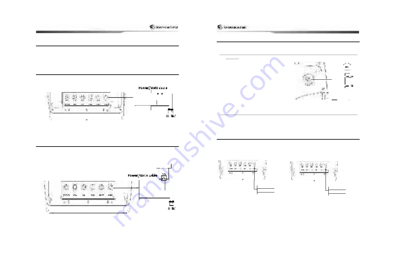
background image


69


5-2 

CONNECTION


GPS Chart plotter has the connection device to connect with the NMEA equipment like power 

supply, GPS antenna, AIS receiver, auto pilot device and digital equipment. 

*Warning:  Check  that  the  power  supply  cable  does  not  get  connected  to  the 

REMOTE Connector or the DATA connector. If power supply cable gets connected to 

the other connector, this will seriously damage the equipment.


5-3 

Power  supply  &  DATA  cable


Manual Power supply 

• For manual power supply, connect the equipment as below 


*Use 7A/250V[30mmX6mm] fuse at 12V power supply   

Use 3A/250V[30mmX6mm] at 24V power supply. 


5-4 

Alert  equipment 


• 

To use the external alert equipment, connect it as shown below 

• The maximum output from equipment to the external alarm is 30V DC 200mA, and you can 

create an environment using appropriate relay. 


PIN No. : 1

PIN No. : 5

FUSE 

2

PIN No. : 8

PIN No. : 5

PIN No. : 1

Alarm 

6

2


User Guide 


70

5-5 

GPS  ANTENNA


\


Selection of antenna 

Install one of the GPS antennas from below. 


5-5-1 

External  antenna                                                                                                                         


Internal GPS antenna’s reception is affected 

by the place where equipment gets installed. 

If the internal GPS antenna’s reception is poor, 

to enhance the GPS signal, you may connect 

the external GPS antenna. You may use BNC 

type of connector to connect.   

Installing external antenna


In case of external antenna needed, install the 

external antenna and connect the antenna 

cable to the display unit. Install the antenna, 

and connect the optional cable if needed. 

System setting of the selected antenna is 

required while installing


5-5-2 

Internal  antenna


The internal antenna is already equipped, 

therefore you may use the equipment without 

external signal input. 


5-6 

NMEA  0183


GPS  chart  plotter  can  be  connected  to  the 

external  equipment  that  uses  NMEA0183  as 

below. 

• DSC VHF Radio 

• GPS antenna(NMEA 0183) 

• NAVTEX 

• AIS RECEIVER 


DSC VHF radio 

Refer  to  the  above  NMEA  0183  picture  to 

install the optional DSC VHF radio 


Other NMEA Equipment


  NMEA is the international industrial standard 

for internal connecting equipment.    This 

equipment can be connected to the NMEA 

equipment. Refer to the above picture when 

connecting other NMEA equipment. 

• Equipment may transmit the GPS location 

and navigational information to the auto 

pilot equipment or other equipment. Auto 

pilot equipment requires NMEA 0183 DATA 

(APB, APA, VTG). 


Please contact SAMYUNGENC for detailed 

information of NMEA data.     

When setting the other equipment to send 

the NMEA data, select the NMEA output and 

PIN No. : 1 (GND) 

PIN No. : 4 (Data in) 

INPUT 
NMEA 0183 

PIN No. : 1 (GND) 

PIN No. : 3 (Data out) 

OUTPUT 
NMEA 0183 

Summary of Contents for NF120

Page 1: ...1 User Guide 2...

Page 2: ...ays may shorten the life of the liquid crystals used in you plotter This limitation is due to the current technology of the LCD display Avoid overheating which may cause loss of contrast and in extrem...

Page 3: ...6 3 Single or Dual Frequency Fish finding 35 3 6 4 Range 35 3 6 5 Gain 36 3 6 6 Sonar window display 37 3 6 7 No plit 37 3 6 8 Split zoom and Full Screen zoom 38 3 6 9 Split bottom 38 User Guide 6 3 6...

Page 4: ...61 4 7 1 Display Filter 62 4 7 2 Alarm Option 62 4 7 3 Display Option 62 4 7 4 Restore Default 62 4 8 Alarm Settings 63 4 8 1 Deep 63 4 8 2 Shallow 63 4 8 3 Temperature 63 4 8 4 Temperature rate 63 4...

Page 5: ...PGN129025 COG SOG Rapid Update PGN129026 GNSS Position Data PGN129029 GNSS DOPs PGN129539 GNSS Sats in View PGN129540 Wind Data PGN130306 Environmental Parameter Water temp PGN130310 Environmental Pa...

Page 6: ...Cover N120 CC Power cable SYCB006C2C P N120 Bracket mounting screw N120 BP Built in kit screw N120 TK Protection Cover N120 CB User Manual N120 MK GPS Antenna SAN 60 10m Quick user guide ENG N120 QSG...

Page 7: ...nit off 2 Turn the bracket mounting knob gently to remove 2 Getting Started User Guide 14 2 2 Buttons FRONT MOB Indicate MOB destination of boat s location Register Create the destination Encoder Used...

Page 8: ...der Sonar when you press it the noise menu pops up The electronic buoy menu appears on the bottom of the screen You may set the track The menu appears on the bottom for you to choose You may use the p...

Page 9: ...SB Slot User Guide 18 2 5 Simulation Simulation Mode is great for practicing the actual use of a product when the satellites signals and internal alarms are not available Under the simulation mode the...

Page 10: ...ass off and on 1 Press and select Data bar 2 Check compass User Guide 20 2 8 Multi Window Display Chart plotter can display up to four windows at a time Adding a window 1 When chart display or any oth...

Page 11: ...display 1 Press twice 2 When window above pops up select a desire display you want Adding a favorite display 1 Organize a window you want 2 Press to view the main window 3 Select Save icon at the bott...

Page 12: ...e GPS chart plotter has been programmed to allow you to view the optimum Chart window Initial setting has been done for the daytime view To change to the Night mode move to Night mode and use or Tip I...

Page 13: ...indow To go to the Chart window Press and select Chart icon A typical Chart window shows Data bar You may change the data displayed on the data bar Compass Chart scale Boat position Boat track Boat co...

Page 14: ...isplay the information To search port service 1 Press 2 Select Find then Port service 3 Select a service you want to find 4 After searching if you select the nearest service cursor will be placed on t...

Page 15: ...s and select the routes window 2 In the route window mover the cursor to highlight a route you want to start navigating to 3 Press and select start 4 Select Forward or Reverse to decide which directio...

Page 16: ...ographical information gets displayed and when navigating both information and mark gets displayed Pitching Display can be tilted From 3D menu use or directional key to place the green mark on the map...

Page 17: ...epeats itself when it ends VOLUME You can adjust the volume of the current playing file When you mute it you can t hear the sound External video It goes to the option where you can use external cam or...

Page 18: ...adjusts the depth automatically for the best performance This option is recommended for normal operation Manual When the mode is set to Manual the unit only displays the depth of water at a given rang...

Page 19: ...ncy is useful for general detection and judging bottom condition High Frequency 200 kHz The 200 kHz frequency is ideal provide a better resolution which means it is ideal for the observation of fish o...

Page 20: ...ing to a destination point To go to the Highway window press and select Highway icon The Highway window shows Compass Data bar Destination waypoint Boat s plotted course to destination DTG scale Dista...

Page 21: ...the existing latitude and longitude to new position 4 Select Save 3 9 3 Editing an existing waypoint To Edit a waypoint from the chart window 1 Move the cursor to the waypoint you want To Edit a wayp...

Page 22: ...rting waypoint in the Route and press 4 Move the cursor keys to the position of next waypoint and press 5 Repeat step 4 to enter more waypoints 6 Once you entered the last waypoint in the route press...

Page 23: ...1 Highlight a route you want to delete 2 Press and select Delete Deleting all route in the route window 1 Press and select Delete All Displaying a route in the Chart window from the route list 1 High...

Page 24: ...S AIS is an Automatic Identification System for identification and localization of boat AIS provide a means for boats to exchange and share boat data including identification position course etc This...

Page 25: ...tress window Displaying a distressed vessel in the chart window 1 Highlight a received distress call you want to display 2 Press and select Display Going to the distress position 1 Highlight a receive...

Page 26: ...he DSC waypoints still exist User Guide 52 3 15 Navtex NAVTEX is an international automated direct printing service for delivery of navigational and meteorological warnings and forecast as well as urg...

Page 27: ...t between S MAP or NAVIONICS chart 4 1 3 Beep volume Select the level of beep sound 4 1 4 Auto power See section 3 1 4 1 5 Features When external devices are connected to the unit the corresponding op...

Page 28: ...s the displaying of Sea Lane on or off 4 2 4 1 Land Sea NAVIONICS Water features Turns the displaying of sea bed nature and tide stations icon on or off Object depths Turns the displaying of object de...

Page 29: ...ause of less power The Auto setting is recommended 4 3 10 Pulse Power You can select specific pulse power of transducer Low power shows a clear display but can t show deeply into the water The Auto se...

Page 30: ...time Press down Or press down Select tracks Plotting interval Remove track Press down Delete Color If you wish to remove all select delete all and you may also delete selected color 4 5 2 Log Reset tr...

Page 31: ...nce from own ship is filtered Filter by speed Vessels with speed below the set value are filtered Show Dangerous Only When this option is selected it shows dangerous vessel only 4 7 2 Alarm Option Dan...

Page 32: ...cer is same as a set value 4 8 4 Temperature rate Trigger an alarm when the rate of temperature change from the transducer is same as a set value 4 8 5 Low battery Trigger an alarm when battery voltag...

Page 33: ...S chart plotter for daylight saving time start and end Time format Select the format of time Date format Select the format of date 4 9 9 Cursor size You can adjust the size of the cursor 4 9 10 Cursor...

Page 34: ...EED SUPPLY 4 TEMP 5 SONAR 6 SONAR GND REMOTE Number of pin Description 1 5V 2 5V GND 3 NC 4 RXD 5 LED_DIM 6 PWR_S W 7 LED_DIM GND User Guide 68 DATA Number of pin Description 1 DGPS_OUT 2 12V 3 12V GN...

Page 35: ...the external GPS antenna You may use BNC type of connector to connect Installing external antenna In case of external antenna needed install the external antenna and connect the antenna cable to the...

Page 36: ...has been applied successfully new set value will be displayed Caution Equipment may apply the WAAS EGNOS DGPS correction value to the other GPS antenna You can acquire more detailed information by con...

Page 37: ...e Main menu 1 Introduction 1 1 General Information 1 2 Specification 1 3 Components 1 4 Optional accessories 2 Getting Started 2 1 Installation 2 1 1 Bracket mounting 2 2 Button 2 3 NAVIONICS SD Card...

Page 38: ...d NAVIONICS 4 2 3 2 Standard S MAP 4 2 4 1 Land Sea NAVIONICS 4 2 4 2 Land Sea S MAP 4 2 5 Map Datum 4 2 6 NMEA Datum offset 4 2 7 Map shift 4 2 8 Restore default User Guide 76 4 3 Sonar setting 4 3 1...

Page 39: ...ude the below chart Item Contents Connector and terminal Check the connectors and terminals on the back of the equipment are normally connected Cable Check the conditions of the cables If the cable ha...

Page 40: ...ue back to 0 Vessel s speed value error is large Adjust the smoothing function to set the value up for the vessel which is slow and set the value low for the vessel which is fast Hard to distinguish t...

Page 41: ...thorized Service Centres SAMYUNG ENC will at its discretion repair or replace any defective products or its components at no cost to you This is your exclusive remedy for defective products Followings...

Page 42: ...83 User Guide 84...

Page 43: ...85...

Reviews: