


3-31
Samsung Electronics
CIRCUIT DESCRIPTION
Repair Manual
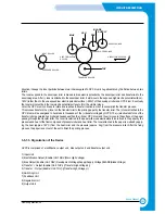
3-5 Engine Controller
3-5-1. FUSER CONTROL / THERMISTOR CIRCUIT
This circuit controls the heat lamp temperature to fix the transferred toner on the paper. It is comprised of the thermistor that
has the negative resistance against the temperature and LM393 (voltage comparator) and transistor for switching.
The thermistor has the resistance value reverse proportional to the heat lamp surface temperature. The voltage value is read
by #60 pin(AVIN2) of CPU refering to the parallel combined resistance with the resistor(R43) connected parallel to it and the
voltage distribution of R29. The voltage read activates (inactivates) ‘fuser’ signal to high (or low) referring to the set tempera-
ture and when the ‘fuseron’ signal turns down(high) to low(high) by Q3 switching, the S21ME4 inside SMPS (PC3) turns
on(off) and this eventually turns two-way thyristor(THY501) on(off) to allow(shut) AC voltage to the heat lamp.
LM393 is a H/W designed to protect the system when the software heat lamp control does not run normal. When the ther-
mistor temperature goes up to 210°C, #1 pin’s level (LM393) will turn low to turn the ‘fuseron’ signal to high. (forcefully shuts
off Q3)In other words LM393 shuts off the heat lamp forcefully.
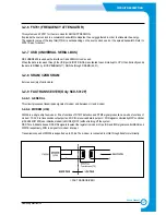
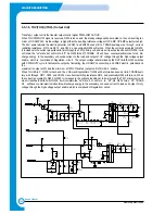
3-5-2. PAPER SENSING CIRCUIT
1) Cover Open Sensing
Cover Open Sensor is located on the right rear side of the printer. In case the right cover is open, it shuts +5V (LSU
laser unit) and +24V( polygon motor of fixer LSU and HVPS) that are supplied to each unit. It detects the cover
opening through CPU. In this case, the red LED of the OP Panel LED will turn on.
2) Paper Empty Sensing
The paper empty sensor (photo interrupter), located inside bottom of the bin cassette detects paper with the actua-
tor connected to it and informs the CPU of whether there is paper. When there is no paper in the cassette, the red
LED of the OP panel LED will turn on to tell the user to fill the cassette with papers.
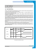
3) Paper Feeding When the paper is fed into the set and passes through the actuator of the feed sensor unit, tran-
sistor inside the photo interrupter will turn on, ‘nFEED’ signal will turn low and inform CPU that the paper is currently
fed into the system. CPU detects this signal and sprays video data after certain time (related to paper adjustment).
If the paper does not hit the feed sensor within certain time, CPU detects this and informs as “Paper Jam0” (red
LED on the OP panel will turn on).
4) Paper Exit Sensing
The system detects the paper going out of the set with the exit sensor assembled to the actuator attached to the
frame. If CPU does not turn back high a while after the paper hits the exit sensor, CPU detects this and inform as
“Paper Jam2” (red LEDs on the OP panel will turn on).
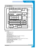
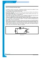
3-5-3. LSU CIRCUIT
1) Polygon Motor Unit (actuated by +24V)
The polygon motor inside LSU rotates by the ‘PMOTOR’ signal. When it reaches the motor constant velocity section
through the initial transient (transient response) section, it sends the ‘nLREADY’ signal to the CPU. The ‘clock’ pin is
the pin that receives clock of the required frequency when LSU uses external CLK as the motor rotational frequen-
cy. Currently the external clock circuit is located in the HVPS and 1686Hz = 6.9083MHz (crystal frequen-
cy)÷4096(74HC4060N IC), is used as the rotational frequency of the polygon motor.
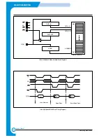
2) Laser Unit (actuated by +5V)
After laser is turned on by ‘nLD_ON’ signal, it is reflected by 6 mirrors (polygon mirror) attached to the polygon motor
and performs scan in horizontal way.When the laser beam hits the corner of the polygon mirror, it generates ‘nHSYNC’
signal (pulse) and the CPU forms the left margin of the image using this signal (horizontal synchronous signal).
Summary of Contents for SF-830
Page 112: ...Exploded Views and Parts List 5 34 Samsung Electronics ...
Page 116: ......
Page 163: ...4 2 SCHEMATIC DIAGRAMS Samsung Electronics Repair Manual Main Circuit Diagram 2 17 ...
Page 164: ...4 3 Samsung Electronics SCHEMATIC DIAGRAMS Repair Manual Main Circuit Diagram 3 17 ...
Page 165: ...4 4 SCHEMATIC DIAGRAMS Samsung Electronics Repair Manual Main Circuit Diagram 4 17 ...
Page 166: ...4 5 Samsung Electronics SCHEMATIC DIAGRAMS Repair Manual Main Circuit Diagram 5 17 ...
Page 167: ...4 6 SCHEMATIC DIAGRAMS Samsung Electronics Repair Manual Main Circuit Diagram 6 17 ...
Page 168: ...4 7 Samsung Electronics SCHEMATIC DIAGRAMS Repair Manual Main Circuit Diagram 7 17 ...
Page 169: ...4 8 SCHEMATIC DIAGRAMS Samsung Electronics Repair Manual Main Circuit Diagram 8 17 ...
Page 170: ...4 9 Samsung Electronics SCHEMATIC DIAGRAMS Repair Manual Main Circuit Diagram 9 17 ...
Page 171: ...4 10 SCHEMATIC DIAGRAMS Samsung Electronics Repair Manual Main Circuit Diagram 10 17 ...
Page 172: ...4 11 Samsung Electronics SCHEMATIC DIAGRAMS Repair Manual Main Circuit Diagram 11 17 ...
Page 173: ...4 12 SCHEMATIC DIAGRAMS Samsung Electronics Repair Manual Main Circuit Diagram 12 17 ...
Page 174: ...4 13 Samsung Electronics SCHEMATIC DIAGRAMS Repair Manual Main Circuit Diagram 13 17 ...
Page 175: ...4 14 SCHEMATIC DIAGRAMS Samsung Electronics Repair Manual Main Circuit Diagram 14 17 ...
Page 176: ...4 15 Samsung Electronics SCHEMATIC DIAGRAMS Repair Manual Main Circuit Diagram 15 17 ...
Page 177: ...4 16 SCHEMATIC DIAGRAMS Samsung Electronics Repair Manual Main Circuit Diagram 16 17 ...
Page 178: ...4 17 Samsung Electronics SCHEMATIC DIAGRAMS Repair Manual Main Circuit Diagram 17 17 ...
Page 180: ...4 19 Samsung Electronics SCHEMATIC DIAGRAMS Repair Manual 4 3 OPE Circuit Diagram D9 ...
Page 181: ...4 20 SCHEMATIC DIAGRAMS Samsung Electronics Repair Manual 4 4 Scan Circuit Diagram ...
Page 187: ...4 26 SCHEMATIC DIAGRAMS Samsung Electronics Repair Manual 4 8 PTL Circuit Diagram ...
Page 188: ...4 27 Samsung Electronics SCHEMATIC DIAGRAMS Repair Manual 4 10 Toner_Rx Circuit Diagram ...
Page 189: ...4 28 SCHEMATIC DIAGRAMS Samsung Electronics Repair Manual 4 11 Toner_Tx Circuit Diagram ...


