3-19
Samsung Electronics
CIRCUIT DESCRIPTION
Repair Manual
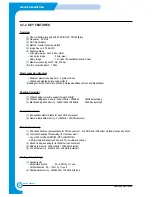
3-2-10-2 Specifications
This section presents the electrical and environmental specifications of the PM-22.
1) Power Ratings
Table presents the PM-22’s minimum and maximum power ratings and storage temperatures.
* VDDBIAS is connected to the system’s 5.0V supply to provide 5V tolerance
on I/O signal pins (including all inputs, outputs, and bidirectionals). in systems
where 3.3V signaling only is used, connect VDDBIAS to a 3.3V supply.
2) Required Operation Conditions
Table presents the PM-22’s environmental specifications.
* VDDBIAS is connected to the system’s 5.0V supply to provide 5V tolerance
on I/O signal pins (including all inputs, outputs, and bidirectionals). in systems
where 3.3V signaling only is used, connect VDDBIAS to a 3.3V supply.
Parameter
Symbol
Min
Max
Units
3.3 Volts Supply Voltage
VDD
-0.3
7.0
Volts
5.0_Volt Reference Level*
3.3_Volt Oper.
VDDBIAS
VDD
3.6
Volts
5.0_Volt Oper.
VDDBIAS
VDD
5.55
Volts
Input pin voltages for other
Vin
-0.3
VDDBIAS + 0.3
Volts
than VDD, VSS
DC Input Current
Iin
-10
+10
mAmps
Storage Temperature
Tas
-40
125
Degrees C
Parameter
Symbol
Min
Max
Units
3.3 Volts Supply Voltage
VDD
3.0
3.6
Volts
5.0_Volt Reference Level*
VDDBIAS
4.75
5.25
Volts
Power Consumption at 66 MHz Operation
Pd
-
1.0
Watt
Operating Temperature
Tao
0
70
Degrees C
Summary of Contents for SF-830
Page 112: ...Exploded Views and Parts List 5 34 Samsung Electronics ...
Page 116: ......
Page 163: ...4 2 SCHEMATIC DIAGRAMS Samsung Electronics Repair Manual Main Circuit Diagram 2 17 ...
Page 164: ...4 3 Samsung Electronics SCHEMATIC DIAGRAMS Repair Manual Main Circuit Diagram 3 17 ...
Page 165: ...4 4 SCHEMATIC DIAGRAMS Samsung Electronics Repair Manual Main Circuit Diagram 4 17 ...
Page 166: ...4 5 Samsung Electronics SCHEMATIC DIAGRAMS Repair Manual Main Circuit Diagram 5 17 ...
Page 167: ...4 6 SCHEMATIC DIAGRAMS Samsung Electronics Repair Manual Main Circuit Diagram 6 17 ...
Page 168: ...4 7 Samsung Electronics SCHEMATIC DIAGRAMS Repair Manual Main Circuit Diagram 7 17 ...
Page 169: ...4 8 SCHEMATIC DIAGRAMS Samsung Electronics Repair Manual Main Circuit Diagram 8 17 ...
Page 170: ...4 9 Samsung Electronics SCHEMATIC DIAGRAMS Repair Manual Main Circuit Diagram 9 17 ...
Page 171: ...4 10 SCHEMATIC DIAGRAMS Samsung Electronics Repair Manual Main Circuit Diagram 10 17 ...
Page 172: ...4 11 Samsung Electronics SCHEMATIC DIAGRAMS Repair Manual Main Circuit Diagram 11 17 ...
Page 173: ...4 12 SCHEMATIC DIAGRAMS Samsung Electronics Repair Manual Main Circuit Diagram 12 17 ...
Page 174: ...4 13 Samsung Electronics SCHEMATIC DIAGRAMS Repair Manual Main Circuit Diagram 13 17 ...
Page 175: ...4 14 SCHEMATIC DIAGRAMS Samsung Electronics Repair Manual Main Circuit Diagram 14 17 ...
Page 176: ...4 15 Samsung Electronics SCHEMATIC DIAGRAMS Repair Manual Main Circuit Diagram 15 17 ...
Page 177: ...4 16 SCHEMATIC DIAGRAMS Samsung Electronics Repair Manual Main Circuit Diagram 16 17 ...
Page 178: ...4 17 Samsung Electronics SCHEMATIC DIAGRAMS Repair Manual Main Circuit Diagram 17 17 ...
Page 180: ...4 19 Samsung Electronics SCHEMATIC DIAGRAMS Repair Manual 4 3 OPE Circuit Diagram D9 ...
Page 181: ...4 20 SCHEMATIC DIAGRAMS Samsung Electronics Repair Manual 4 4 Scan Circuit Diagram ...
Page 187: ...4 26 SCHEMATIC DIAGRAMS Samsung Electronics Repair Manual 4 8 PTL Circuit Diagram ...
Page 188: ...4 27 Samsung Electronics SCHEMATIC DIAGRAMS Repair Manual 4 10 Toner_Rx Circuit Diagram ...
Page 189: ...4 28 SCHEMATIC DIAGRAMS Samsung Electronics Repair Manual 4 11 Toner_Tx Circuit Diagram ...

