


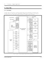

4. Theory of Operation
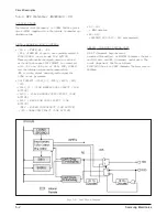
4-1 Engine Configuration
4-1-1 Video Controller Board
Video Controller Board receives image data from the
host computer and converts them to a
bitmap(binary) image, which is sent to the
Engine(Controller) Board.
4-1-2 Engine Controller Board
Engine Board receives the video data from the
Controller Board, and then that sends current image
to LSU and controls the electrophotography process
for printing.
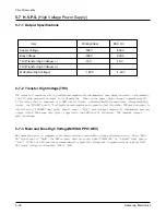
4-1-3 HVPS Board
HVPS board generates THV/MHV/BIAS high
voltages, apply it to Developer unit. And LSU,
Cover Open Sensor interface signals connect via this
board from Engine Control Board to each units.
4-1-4 Joint Board
Joint Board Contains Main Motor and Clutch and
Pre-Transfer Lamp driving circuit, New Developer
and Paper Empty, Paper Exit Sensing circuit, and
connects with Engine Controller Board.
4-1-5 Developer Cartridge
Developer (Cartridge) creates the image via the
electrophotography process. The Charge Roller,
OPC Drum, Developer Roller, Supply Roller and
Toner constitute a single unit.
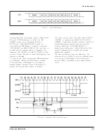
4-1-6 LSU(Laser Scanner Unit)
Under control of the Engine, controls the laser beam
and the OPC Drum exposure and rotation. The OPC
Drum is synchronized and rotating with the same
speed as the paper. When laser beam reaches the
position of the Scanning Mirror, it creates a line.
Synchronization Signal(HSYNC), which is sent to
the Engine Board which transfers image data to LSU
and synchronizes the vertical scanning line with the
printed page.
4-1-7 Transfer
It constitutes the PTL(Pre-transfer Lamp) and the
Transfer Roller. The PTL exposes the light to the
OPC drum and lowers the OPC drum surface
potential, and transfer efficiency become higher. The
Transfer Roller transfers Toner on the OPC Drum to
the paper.
4-1-8 Fuser
It constitutes the Heat Lamp, Heat Roller, Pressure
Roller and Thermistor, thermostat, and causes the
Toner to adhere to the paper.
Samsung Electronics
4-1
Summary of Contents for MSYS 5150
Page 9: ...2 6 Samsung Electronics Specification Memo ...
Page 16: ...3 26 Samsung Electronics Setup and Installing Memo ...
Page 37: ...4 2 Samsung Electronics Theory of Operation ...
Page 41: ...4 6 Samsung Electronics Memo Theory of Operation ...
Page 116: ...Samsung Electronics 7 9 Maintenance Troubleshooting No Image ...
Page 117: ...Samsung Electronics Maintenance Troubleshooting 7 10 ...
Page 118: ...Samsung Electronics 7 11 Maintenance Troubleshooting All Black ...
Page 119: ...7 12 Samsung Electronics Maintenance Troubleshooting Vertical White Line Band ...
Page 120: ...Samsung Electronics 7 13 Maintenance Troubleshooting Dark Image ...
Page 121: ...7 14 Samsung Electronics Maintenance Troubleshooting Background ...
Page 122: ...Samsung Electronics 7 15 Maintenance Troubleshooting Ghost ...
Page 123: ...7 16 Samsung Electronics Maintenance Troubleshooting Black Dot ...
Page 124: ...Samsung Electronics 7 17 Maintenance Troubleshooting Horizontal Band ...
Page 125: ...7 18 Samsung Electronics Maintenance Troubleshooting Irregular Density ...
Page 126: ...Samsung Electronics 7 19 Maintenance Troubleshooting White Spot ...
Page 127: ...7 20 Samsung Electronics Maintenance Troubleshooting Trembling at the End When OHP Printing ...
Page 128: ...Samsung Electronics 7 21 Maintenance Troubleshooting Poor Fusing Grade ...
Page 132: ...Samsung Electronics 7 25 Maintenance Troubleshooting No Power LCD NO display LED Off ...
Page 133: ...Fuser Error 7 26 Samsung Electronics Maintenance Troubleshooting ...
Page 134: ...Samsung Electronics 7 27 Maintenance Troubleshooting Paper Jam Mis feeding ...
Page 135: ...7 28 Samsung Electronics Maintenance Troubleshooting Paper Jam Jam1 ...
Page 136: ...Samsung Electronics Maintenance Troubleshooting 7 29 Engine Error ...
Page 137: ...7 30 Samsung Electronics Maintenance Troubleshooting Memo ...
Page 187: ...9 28 Samsung Electronics Electrical Parts List ...
Page 189: ...11 Connection Diagram Samsung Electronics 11 1 ...
Page 190: ...12 1 Main Circuit Diagram Samsung Electronics 12 1 12 Schematic Diagrams ...
Page 191: ...Schematic Diagrams 12 2 Samsung Electronics Main Circuit Diagram ...
Page 192: ...Main Circuit Diagram Samsung Electronics 12 3 Schematic Diagrams ...
Page 193: ...Schematic Diagrams 12 4 Samsung Electronics Main Circuit Diagram ...
Page 194: ...Main Circuit Diagram Samsung Electronics 12 5 Schematic Diagrams ...
Page 195: ...Schematic Diagrams 12 6 Samsung Electronics Main Circuit Diagram ...
Page 196: ...Main Circuit Diagram Samsung Electronics 12 7 Schematic Diagrams ...
Page 200: ...12 3 Sensors Circuit Diagram Samsung Electronics 12 11 Schematic Diagrams ...
Page 201: ...Schematic Diagrams 12 12 Samsung Electronics 12 4 Switch Circuit Diagram ...
Page 202: ...Samsung Electronics 12 13 Schematic Diagrams 12 5 Joint Circuit Diagram ...
Page 204: ...Samsung Electronics 12 15 Schematic Diagrams 12 7 PTL Circuit Diagram ...
Page 205: ...Schematic Diagrams 12 16 Samsung Electronics 12 8 SCAN Circuit Diagram ...
Page 206: ...Samsung Electronics 12 17 Schematic Diagrams 12 9 Engin Circuit Diagram ...
Page 207: ...Schematic Diagrams 12 18 Samsung Electronics Engin Circuit Diagram ...
Page 208: ...Samsung Electronics 12 19 Schematic Diagrams 12 10 LIU Circuit Diagram ...
Page 210: ... Samsung Electronics Co Ltd Mar 1999 Printed in Korea P N JC68 00097A Rev 1 00 ELECTRONICS ...