7-6
Samsung Electronics
Maintenance & Troubleshooting
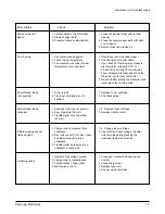
7-3 Print Quality
Error Status
Check
Solution
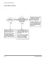
Vertical black line and band
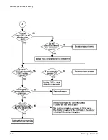
Vertical white line
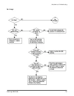
No image
Light image
Dark image
Background
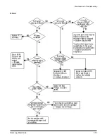
Ghost
1. Change Toner cartridge
2. Replace LSU
1. Clean LSU window
2. If not LSU, change Toner cartridge
1. Removing seal tipe
2. Measure the resistance between frame
ground and the ground spring attached
frame. Confirm stable ground. Unless
bad ground, detach cabinet, check where
is bad point
3.Adjust LSU or replace it
4. Normal Dev bias = -300V
5. Shake toner cartridge and print.If a liitke
good, toner is empty
6. Test engine test pattern with DCU,
replace Video board
1. Check and remove tape
2. LSU light power check is difficult.
Compare with new one and check.
3. Check toner and developer counter
4~5. Measure all high voltage output
6. Leakage toner cause bad contact and
increase contact resistance. Clean
contaminated area.
1. Check the rated level and replace
2. Set to power rating
3. Replace defected board
1. Adjust to the rated status
2. Replace Toner cartridge
1. Check every high voltage
2. Check the turn-on PTL, LED crash
3. Clean the inside machine or replace
toner cartridge
1. Bad blade of Toner cartridge
2. LSU
1. LSU window contamination
2. Toner cartridge
1. Seal tape is removed?
2. GND OPC is well grounded?
3. LSU running well?
4. Biss voltage is normal?
5. Lower toner?
6. Is there video data from controller?
1. Check seal tape removing
2. LSU light power normal?
3. Enough toner?
4. High charger voltage?
5. Lower bias voltage
6. Contamination of high voltage
contact
7. Transfer volatge and roller
1. LSU light power normal?
2. Bias voltage output is high?
3. Video data is always supplied?
1. High voltage output is normal?
2. C/R of Toner cartridge is
contaminated?
1. High voltage output
2. Pre-Transfer Lamp
3. Bad high voltage contact
Summary of Contents for MSYS 5150
Page 9: ...2 6 Samsung Electronics Specification Memo ...
Page 16: ...3 26 Samsung Electronics Setup and Installing Memo ...
Page 37: ...4 2 Samsung Electronics Theory of Operation ...
Page 41: ...4 6 Samsung Electronics Memo Theory of Operation ...
Page 116: ...Samsung Electronics 7 9 Maintenance Troubleshooting No Image ...
Page 117: ...Samsung Electronics Maintenance Troubleshooting 7 10 ...
Page 118: ...Samsung Electronics 7 11 Maintenance Troubleshooting All Black ...
Page 119: ...7 12 Samsung Electronics Maintenance Troubleshooting Vertical White Line Band ...
Page 120: ...Samsung Electronics 7 13 Maintenance Troubleshooting Dark Image ...
Page 121: ...7 14 Samsung Electronics Maintenance Troubleshooting Background ...
Page 122: ...Samsung Electronics 7 15 Maintenance Troubleshooting Ghost ...
Page 123: ...7 16 Samsung Electronics Maintenance Troubleshooting Black Dot ...
Page 124: ...Samsung Electronics 7 17 Maintenance Troubleshooting Horizontal Band ...
Page 125: ...7 18 Samsung Electronics Maintenance Troubleshooting Irregular Density ...
Page 126: ...Samsung Electronics 7 19 Maintenance Troubleshooting White Spot ...
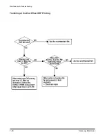
Page 127: ...7 20 Samsung Electronics Maintenance Troubleshooting Trembling at the End When OHP Printing ...
Page 128: ...Samsung Electronics 7 21 Maintenance Troubleshooting Poor Fusing Grade ...
Page 132: ...Samsung Electronics 7 25 Maintenance Troubleshooting No Power LCD NO display LED Off ...
Page 133: ...Fuser Error 7 26 Samsung Electronics Maintenance Troubleshooting ...
Page 134: ...Samsung Electronics 7 27 Maintenance Troubleshooting Paper Jam Mis feeding ...
Page 135: ...7 28 Samsung Electronics Maintenance Troubleshooting Paper Jam Jam1 ...
Page 136: ...Samsung Electronics Maintenance Troubleshooting 7 29 Engine Error ...
Page 137: ...7 30 Samsung Electronics Maintenance Troubleshooting Memo ...
Page 187: ...9 28 Samsung Electronics Electrical Parts List ...
Page 189: ...11 Connection Diagram Samsung Electronics 11 1 ...
Page 190: ...12 1 Main Circuit Diagram Samsung Electronics 12 1 12 Schematic Diagrams ...
Page 191: ...Schematic Diagrams 12 2 Samsung Electronics Main Circuit Diagram ...
Page 192: ...Main Circuit Diagram Samsung Electronics 12 3 Schematic Diagrams ...
Page 193: ...Schematic Diagrams 12 4 Samsung Electronics Main Circuit Diagram ...
Page 194: ...Main Circuit Diagram Samsung Electronics 12 5 Schematic Diagrams ...
Page 195: ...Schematic Diagrams 12 6 Samsung Electronics Main Circuit Diagram ...
Page 196: ...Main Circuit Diagram Samsung Electronics 12 7 Schematic Diagrams ...
Page 200: ...12 3 Sensors Circuit Diagram Samsung Electronics 12 11 Schematic Diagrams ...
Page 201: ...Schematic Diagrams 12 12 Samsung Electronics 12 4 Switch Circuit Diagram ...
Page 202: ...Samsung Electronics 12 13 Schematic Diagrams 12 5 Joint Circuit Diagram ...
Page 204: ...Samsung Electronics 12 15 Schematic Diagrams 12 7 PTL Circuit Diagram ...
Page 205: ...Schematic Diagrams 12 16 Samsung Electronics 12 8 SCAN Circuit Diagram ...
Page 206: ...Samsung Electronics 12 17 Schematic Diagrams 12 9 Engin Circuit Diagram ...
Page 207: ...Schematic Diagrams 12 18 Samsung Electronics Engin Circuit Diagram ...
Page 208: ...Samsung Electronics 12 19 Schematic Diagrams 12 10 LIU Circuit Diagram ...
Page 210: ... Samsung Electronics Co Ltd Mar 1999 Printed in Korea P N JC68 00097A Rev 1 00 ELECTRONICS ...


