background image

Product Specification and feature

Service Manual

2-18

Samsung Electronics

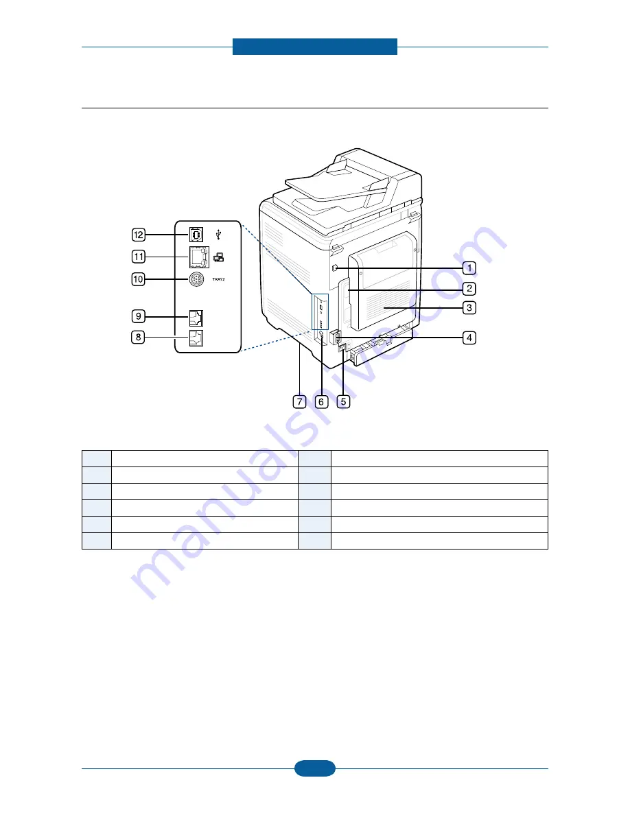
2.4.1.2 Rear view

1

External device interface (EDI)

a

7

Handle

2

Control board cover

8

Extension telephone socket (EXT)

3

Rear door

9

Telephone line socket

4

Cable organizer

10

Optional tray 2 cable connector

5

Power receptacle

11

Network port

6

Power-switch

12

USB port

a. External device interface for Samsung and third party solutions. (CLX-6250 Series only).

Summary of Contents for CLX-6220FX

Page 1: ... Letter Printing resolution up to 9600x600 dpi effective output CPU CLX 6220FX 360MHz CLX 6250FX 700MHz Toner cartridge Initial black color 2 5K 2K 6220FX 5K 4K 6250FX Paper handling Max 850 sheets paper capacity 250 sheets cassette 500 sheets option cassette MP tray 100 sheets Memory 256MB Max 768MB 6250FX 512MB 6220FX Network USB 2 0 4 Line LCD The keynote of Product ...

Page 2: ...6 FAX 2 8 2 2 7 Paper Handling 2 10 2 2 8 Consumables 2 11 2 2 9 Maintenance parts 2 12 2 2 10 Reliability Service 2 13 2 2 11 Environment 2 14 2 2 12 Packing Accessory 2 14 2 2 13 Option 2 15 2 3 Model Comparison 2 16 2 4 Product configuration 2 17 2 4 1 Printer external 2 17 2 4 2 Hardware configuration 2 22 2 4 3 Feeding Section 2 36 2 4 4 LSU 2 37 2 4 5 Fuser Unit 2 38 2 4 6 PTB Paper Transfer...

Page 3: ...assembly 3 4 3 3 1 Cover Unit 3 4 3 3 2 Scanner Ass y 3 8 3 3 3 DADF 3 12 3 3 4 Reverse Ass y 3 13 3 3 5 Cover Middle Ass y 3 14 3 3 6 HVPS Board 3 15 3 3 7 Main board 3 16 3 3 8 SMPS Board 3 16 3 3 9 Fuser Control Board 3 17 3 3 10 LSU 3 17 3 3 11 SOLENOID 3 18 3 3 12 Drive Exit Bracket 3 19 3 3 13 Drive Fuser Bracket 3 20 4 1 Alignment and Adjustments 4 1 4 1 1 Control Panel 4 1 4 1 2 Understand...

Page 4: ...lutions 4 70 4 2 5 Common Problems and solutions 4 77 4 2 6 Network problems and solutions 4 78 4 2 7 Copy Problems 4 80 4 2 8 OPE Problems 4 83 5 1 Block Diagram 5 1 5 1 1 6250FX 5 1 5 1 2 6220FX 5 2 5 1 3 OPE 5 3 5 2 Connection diagram 5 4 6 1 Tools for Troubleshooting 6 1 6 2 Acronyms and Abbreviations 6 2 6 3 Select a location for the printer 6 4 6 4 A4 ISO 19752 Standard Pattern 6 5 Contents ...

Page 5: ...ctric shocks or fire hazards 3 Laser Safety Statement The product is certified in the U S to conform to the requirements of DHHS 21 CFR chapter 1 Subchapter J for Class 1 1 laser products and elsewhere it is certified as a Class I laser product con forming to the requirements of IEC 825 Class I laser products are not considered to be hazardous The laser system and product are designed so there is ...

Page 6: ...ng the power connector When removing the power connector grip it firmly and pull The power connector must be inserted completely otherwise a poor contact could cause overheating possibly leading to a fire 7 Take care of the power cable Do not allow it to become twisted bent sharply around corners or wise damaged Do not place objects on top of the power cable If the power cable is damaged it could ...

Page 7: ...carry out the following procedures before dismantling the product or replacing any parts 1 Check the contents of the machine memory and make a note of any user settings These will be erased if the main board or network card is replaced 2 Ensure that power is disconnected before servicing or replacing any electrical parts 3 Disconnect interface cables and power cables 4 Only use approved spare part...

Page 8: ...ng the product When transporting installing the equipment employ four persons and be sure to hold the lifting handles Be sure not to hold the movable parts or units e g the control panel DADF when transporting the equipment Be sure to use a dedicated outlet with 110V 220V power input The equipment must be grounded for safety Select a suitable place for installation Avoid excessive heat high humidi...

Page 9: ...oam to prevent electrostatic charge buildup in the vicinity of the assembly 3 Use only a grounded tip soldering iron to solder or desolder ESDs 4 Use only an anti static solder removal device Some solder removal devices not classified as anti static can generate electrical charges sufficient to damage ESDs 5 Do not use Freon propelled chemicals When sprayed these can generate electrical charges su...

Page 10: ...olor 24 ppm A4 25ppm Letter Printing resolution up to 9600x600 dpi effective output CPU CLX 6220FX 360MHz CLX 6250FX 700MHz Toner cartridge Initial black color 2 5K 2K 6220FX 5K 4K 6250FX Machine Life 200K or 5 years Paper handling Max 850 sheets paper capacity 250 sheets cassette 500 sheets option cassette MP tray 100 sheets Memory 256MB Max 768MB 6250FX 512MB 6220FX Network USB 2 0 4 Line LCD CL...

Page 11: ...tter Duplex B W Up to 10ipm in A4 10 ipm in Letter Color Up to 10ipm in A4 10 ipm in Letter B W Up to 12 ipm in A4 12ipm in Letter Color Up to 12 ipm in A4 12ipm in Letter Warmup time Less than 27 sec Less than 19 5 sec FPOT B W From Ready Less than 24 sec Less than 24 sec From Sleep Less than 24 sec Less than 24 sec FPOT Color From Ready Less than 24 sec Less than 24 sec From Sleep Less than 24 s...

Page 12: ...penSuSE9 1 9 2 9 3 10 0 10 1 10 2 10 3 11 0 SuSE Enterprise Desktop 9 10 Ubuntu6 04 6 10 7 04 7 10 8 04 Mandriva10 0 10 1 2005 2006 2007 2008 Debian3 1 4 0 Mac OS X 10 3 10 5 Mac OS X 10 3 10 5 Default Driver SPL C Samsung Printer Language Color PCL6 WHQL Windows 2000 XP 2003 Vista include 64bit Windows 2000 XP 2003 Vista include 64bit Scan driver TWAIN Yes Windows Mac Linux Yes Windows Mac Linux ...

Page 13: ...10 1 2005 2006 2007 2008 Debian3 1 4 0 Windows 2000 XP 32 64bit 2003 Server 32 64bit Vista Server 32 64bit NetWare 5 x 6 x Mac OS X 10 3 10 5 TCP IP Only Redhat Enterprise Linux WS4 5 Fedora2 3 4 5 6 7 8 9 openSuSE9 1 9 2 9 3 10 0 10 1 10 2 10 3 11 0 SuSE Enterprise Desktop 9 10 Ubuntu6 04 6 10 7 04 7 10 8 04 Mandriva10 0 10 1 2005 2006 2007 2008 Debian3 1 4 0 2 2 3 Interface Item CLX 6220FX CLX 6...

Page 14: ... 356mm 14 DADF Max 297mm 11 7 platen 356mm 14 DADF Effiective Scan Length Max 289mm platen 348mm DADF Max 289mm platen 348mm ADF Scan Depth Color Inernal 36 bit External 24bit Inernal 36 bit External 24bit Mono 1bit for Linearity Halftone 8Bit for Gray scale 1bit for Linearity Halftone 8Bit for Gray scale Scan Function Scan to USB SMB FTP Network Email Scan to USB SMB FTP Network Email Compatibili...

Page 15: ...dpi Scan 600x600dpi Optical 600x600dpi Platen Printing 600x600dpi Text Photo default Scan 600x600dpi Optical 300x300dpi ADF Printing 600x600dpi Scan 600x600dpi Optical 600x600dpi Platen Printing 600x600dpi Scan 600x600dpi Optical 300x300dpi ADF Printing 600x600dpi Scan 600x600dpi Optical 600x600dpi Platen Printing 600x600dpi Magazine Scan 600x600dpi Optical 300x300dpi ADF Printing 600x600dpi Scan ...

Page 16: ...y ID Card Copy Yes Platen Only Yes Platen Only Auto fit Yes Platen Only Yes Platen Only Margin Shift Yes Yes Book Copy Yes Yes Auto Suppression Yes Yes Covers No No Transparencies No No Create Booklet No No N up copy 2 up 4 up 2 up 4 up Clone Yes Platen Only Yes Platen Only Poster Yes Platen Only Yes Platen Only ...

Page 17: ...n Any Reserved Transmission are not supported ECM Yes Yes Resolution Mono Std 203 x 98 dpi 203 x 98 dpi Fine 203 x 196 dpi 203 x 196 dpi S Fine 300 x 300 dpi 300 x 300 dpi Resolution Color Std 200 x 200 dpi 200 x 200 dpi Fine 200 x 200 dpi 200 x 200 dpi S Fine 200 x 200 dpi 200 x 200 dpi Scan speed 3 6 sec Letter Mono scan time 3sec Letter Mono scan time Telephone Features Handset No No On hook Di...

Page 18: ...HIGH Yes Off LOW MED HIGH Key Volume Yes On Off Yes On Off Speaker Yes On Off Comm Yes On Off Comm Alarm Volume Yes On Off Yes On Off Junk Fax barrier Yes Yes Security Receive Yes Yes Fax Memory Backup Yes Serial flash Yes Built in HDD Receive Mode Fax TEL Ans Fax Fax TEL Ans Fax Capacity less than 4 MB 200 Pages Mono less than 4 MB 200 Pages Mono Optional Memory No No Max locations to store to 1 ...

Page 19: ... Color Paper Envelope Recycled Media weight 16 59 lb 60 to 220 g 16 59 lb 60 to 220 g Sensing Empty sensing No size sensor Empty sensing No size sensor Standard Cassette Tray Capacity 250 sheets 80g 250 sheets 80g Media sizes 76 x127mm 3 x 5 216 x 356mm 8 5 x 14 76 x127mm 3 x 5 216 x 356mm 8 5 x 14 Media types Plain paper Plain paper Media weight 16 28lb 60 to 105g 16 28lb 60 to 105g Size sensor N...

Page 20: ...0FX CLX 6250FX Toner cartridge Yield Initial 2 5K 2K Black Color Sales 5K 4K Black Color 2 5K 2K Black Color Initial 5K 4K Black Color Sales 5K 4K Black Color 2 5K 2K Black Color Model Standard yield CLT C508S Cyan CLT M508S Magenta CLT Y508S Yellow CLT K508S Black High yield CLT C508L Cyan CLT M508L Magenta CLT Y508L Yellow CLT K508L Black Standard yield CLT C508S Cyan CLT M508S Magenta CLT Y508S...

Page 21: ...Maintenance parts Item Image Part Code Life Fuser unit JC91 00970A 6220_110V JC91 00971A 6220_220V JC91 00968A 6250_110V JC91 00969A 6250_220V 100K Pick up roller JC90 00932A 70K Cassette holder pad JC90 00993A 70K ADF Pick up Roller JC97 03070A 80K ADF Friction Pad JC97 03069A 20K ...

Page 22: ...ges 65 000 pages 80 000 pages 58 000 pages 58 000 pages 30 min 30 min Yes Yes Configuration Sheet Demo Sheet Configuration Sheet Demo Sheet Comm Mode N A N A Operation N A N A Operating 15 32 5 59 90 5 15 32 5 59 90 5 Storage 20 40 4 104 20 40 4 104 Operating 10 80RH 10 80RH Storage 0 95RH 0 95RH Test Print RDC Temperature Humidity Item Printing Volume AMPV Max Monthly Duty MPBF MTTR Real time Clo...

Page 23: ...than 35Wh Less than 40Wh Sleep Less than 12Wh Less than 13Wh Dimension W x D x H Set 468 x 498 x 651 mm 18 43 x 19 61 x 25 63 in 468 x 498 x 651mm 18 43 x 19 61 x 25 63 in Weight Set with consumables 36kg 79 4lb 37kg 81 6lb Set Packing 44kg 97lb 45kg 99 2lb Consumables 1 08kg 2 38 lb 1 2kg 2 65 lb Consumables Packing 1 6 Kg 3 53 lb 1 7 Kg 3 75 lb 2 2 12 Packing Accessory Item CLX 6220FX CLX 6250FX...

Page 24: ...tion Item CLX 6220FX CLX 6250FX Memory CLP MEM201 128 MB CLP MEM202 256 MB CLP MEM150 128 MB CLP MEM160 256 MB CLP MEM170 512 MB Second Cassette CLX S6250A 500 sheet cassette CLX S6250A 500 sheet cassette Wireless Network N A ML NWA40L Tall Stand N A N A Hard Disk N A ML HDK300 160GB ...

Page 25: ...12 256 Max 784 160 Max 418 FPOT Less than 27 seconds Less than 19 5 seconds Less than 18 seconds Network Standard Standard Standard Duplex printing Standard Standard Standard Scan System CCD CCD CCD HDD N A 160GB option Paper Capacity 250 CST 100 MP 250 CST 100 MP 250 CST 50 MP Toner cartridge Standard Black Color 2 5K 2K High Black Color 5K 4K Standard Black Color 2 5K 2K High Black Color 5K 4K S...

Page 26: ...icator 15 Multi purpose tray paper width guides 2 Document feeder width guides 9 Optional tray 2a 16 Toner cartridges 3 Document feeder input tray 10 Tray 1 17 Paper transfer belt 4 Document feeder output tray 11 Multi purpose tray 18 Scanner lid 5 USB memory port 12 Front door 19 Scanner lock switch 6 Front door handle 13 Document output tray 20 Scanner glass 7 Multi purpose tray handle 14 Contro...

Page 27: ...erface EDI a 7 Handle 2 Control board cover 8 Extension telephone socket EXT 3 Rear door 9 Telephone line socket 4 Cable organizer 10 Optional tray 2 cable connector 5 Power receptacle 11 Network port 6 Power switch 12 USB port a External device interface for Samsung and third party solutions CLX 6250 Series only ...

Page 28: ...em No Item 1 LSU 7 SCF Unit Option cassette 13 Main PBA 2 Toner cartridge K 8 Pick up Roller SMPS PBA 3 Toner cartridge C 9 Exit Roller FDB Fuser Drive Board PBA 4 Toner cartridge M 10 Reverse Unit 14 Scanner Platen unit 5 Toner cartridge Y 11 Fuser Unit 15 DADF unit 6 Cassette 12 PTB Unit Paper transfer belt ...

Page 29: ...ectronics 2 4 1 4 Paper path Engine paper path SCF1 Feed SCF1 Feed SCF1 Feed SCF1 Feed SimplexPass Duplex Pass MP Feed SimplexPass Duplex Pass MP Feed SimplexPass Duplex Pass MP Feed SimplexPass SimplexPass Duplex Pass MP Feed Duplex Pass Duplex Pass MP Feed MP Feed ...

Page 30: ...Product Specification and feature Service Manual 2 21 Samsung Electronics DADF paper path Middle Roll Exit Roll Dadf Pickup Roll Regi Roll Scan Area CCD Simples Duplex ...

Page 31: ...Product Specification and feature Service Manual 2 22 Samsung Electronics SMPS Main Board HVPS FDB Reverse USB Host Panel Scan Joint DADF 2 4 2 Hardware configuration ...

Page 32: ...3 22 24 25 26 27 28 29 30 1 2 3 4 5 6 7 8 20 1 11 2 12 10 3 9 8 4 7 6 5 13 14 15 16 17 18 19 21 23 22 24 25 26 27 28 29 30 1 2 3 4 5 6 7 8 NO Connector NO Connector NO Connector 1 BLDC DEVE 12pin 11 HVPS2 21 STEP MOTOR reserved 2 BLDC OPC 10pin 12 24V SWITCH 22 C K LSU 20pin 3 PTB 14pin 13 DEBUG 4pin 23 Y M LSU 20pin 4 FAN reserved 3pin 14 PTL 8pin 24 FEED STEP 4pin 5 DEVE CRUM 7pin 15 FAN reserve...

Page 33: ...514 HDD OPTION LPEC3 ASIC Engine Control DDR SODIMM On board M U X SMPS TYPE4 STAGE3 POWER CORD POWER CORD POWER CORD FUSER Lamp Control Motor OPC BLDC DEVE BLDC FUSER BLDC FEED STEP MOTOR EXIT STEP MOTOR Solenoid Clutch CST Pickup Solenoid DEVE K Clutch Fan Fuser Fan Rear Fan PTB UNIT DEVE CRUM IF PBA CRUM ACR sensor L R DEVE Y UNIT CRUM DEVE M UNIT CRUM DEVE C UNIT CRUM DEVE K UNIT CRUM DEVE Y U...

Page 34: ...DRAM Size CLX 6250FX DDR2 Default 256MB on board Option 128MB 256MB 512MB EEPROM Size 512kb Interface With SPGPV4 I2C Controller CRUM Size 256Byte Interface With LPEC3I2C Controller via Deve Crum IF B D I O Interface USB DEVICE High Speed USB 2 0 High speed 480Mbps N W Embedded SPGPV4 With MII Interface Active LED Yellow Link LED Green PWM High Voltage Control With Duty Main Motor Clock I2C Interf...

Page 35: ...OPC 10pin 17 REAR FAN 3pin 3 PTB 14pin 18 SMPS TYPE5 28pin 4 FAN reserved 3pin 19 LSU MOTOR 10pin 5 DEVE CRUM 7pin 20 TEMP_LSU 2pin 6 SENSER TEMP 8pin 21 STEP MOTOR reserved 7 BLDC FUSER 15pin 22 C K LSU 20pin 8 FUSER THERMISTOR 4pin 23 Y M LSU 20pin 9 CURL SENSOR reserved 3pin 24 FEED STEP 4pin 10 HVPS1 25 FUSER HEAT CONTROL 6pin 11 HVPS2 26 SCF JACK 12 24V SWITCH 27 ETHERNET JACK 13 DEBUG 4pin 2...

Page 36: ...JOINT DADF REVERSE CCD FAX HOST USB SMPS Fan LPEC3 ASIC Engine Control DDR SODIMM On board M U X SMPS TYPE5 STAGE3 POWER CORD POWER CORD POWER CORD FUSER Lamp Control Motor OPC BLDC DEVE BLDC FUSER BLDC FEED STEP MOTOR EXIT STEP MOTOR Solenoid Clutch CST Pickup Solenoid DEVE K Clutch Fan Fuser Fan Rear Fan PTB UNIT DEVE CRUM IF PBA CRUM ACR sensor L R DEVE Y UNIT CRUM DEVE M UNIT CRUM DEVE C UNIT ...

Page 37: ...lash used 8MB SDRAM Size Default 256MB on board Option 128MB 256MB 512MB EEPROM Size 512kb Interface With Chorus3 I2C Controller CRUM Size 256Byte Interface With LPEC3I2C Controller via Deve Crum IF B D I O Interface USB DEVICE High Speed USB 2 0 High speed 480Mbps N W Embedded SPGPV4 With MII Interface Active LED Yellow Link LED Green PWM High Voltage Control With Duty Main Motor Clock I2C Interf...

Page 38: ...type 24V For use Mechanical Part Motor Actuator Solenoid Clutch 5V Logic Analog Sensor HVPS LPEC3 SMPS Type 5 PTB unit 5V 5V_SMPS 24V2 24V1 5VS Cover open Switch relay 24V1 24VS1 24V2 24VS2 5VL 5VLSU 24VS1 24VS2 3 3V_CRUM 3 3V 24V_ENABLE OPC BLDC Fuser BLDC EXIT Step Motor MP solenoid Pickup solenoid Deve K clutch SCF FAN_REAR 24V2 DEV CRUM LSU LD BD FDB FUSER_ON DEVE BLDC FEED Step Motor LSU_MOTO...

Page 39: ...Main Board and other boards through a Main Controller by 5V 24V from 110V 220V power input It has safety protection modes for over current and load Connection 1 INPUT_AC from Fuser Drive Board 2 OUTPUT_5V 24V to Main PBA INPUT_24V_Control from Main PBA SPECIFICATION General Input Output Voltage 1 AC 110V 90V 135V 2 AC 220V 180V 270V 3 Output Power 192W Max 270W DC 5V 24W 30W DC 24V 168W 240W ...

Page 40: ...n Power 24V1 1 2 GND 24V Ground Power 24V1 3 4 24V1 Power 24V Ground GND 5 6 GND 24V Ground Power 24V2 7 8 GND 24V Ground Power 24V2 9 10 24V2 Power 24V Ground GND 11 12 GND 24V Ground Power 24V3 13 14 GND 24V Ground Power 24V3 15 16 GND 24V Ground 5V Ground GND 17 18 GND 5V Ground Power 5V1 19 20 GND 5V Ground Power 5V1 21 22 5V1 Power 5V Ground GND 23 24 GND 5V Ground Power 5V2 25 26 5V2 Power S...

Page 41: ...R 2 HVPS has a Cover Open switch and some connectors from Ope PBA feed exit cst_empty cst_detect MP_empty sensor MP clutch and Erase Lamp 4EA 1 EXIT SENSOR 2 24V SWITCH 3 HVPS1 from Main Board 4 HVPS2 from Main Board 5 Feed CST empty sensor 6 MP solenoid MP empty CST detect 7 Fuser bias Connection 2 3 4 5 6 7 8 COVER OPEN SWITCH ATTR ERASER DEV SUPPLY CHARGER 1 2 3 4 5 6 7 COVER OPEN SWITCH ATTR T...

Page 42: ...90M 14uA 0 35uA 0 3kV ATTR DC 1 Constant V PWM duty 100M 1418V 0 3500V 0 30uA DC Constant V Enable 25M 800V 0 30uA Fuser Bias DC 1 Constant V PWM duty 100M 418V 0 900V 0 20uA ATTR_P 108 42 1418V 100M 100M 100M 100M 100M 0 85V 66 ATTR_N on 800 25M 25M 25M 25M 25M Fuser Bias 128 50 418V 100M 100M 100M 100M 100M Constant current outputs in T1 channels Individual T1 channels for each color AC DC deve ...

Page 43: ...E PBA and supplies AC power to the SMPS Both V1 V2 FDBs provide max 1500W output power Connection 1 INLET AC 2 FUSER CONTROL from Main board 3 FUSER AC to Fuser lamp 4 SMPS AC to SMPS Specification V1 V2 Input Voltage Range AC 110V 90 135V AC 220V 180 270V Input Current 20A 10A Output Power Max 1300W Max 1300W Phase Detect Not support Protection Relay Control Signal 3 4 2 1 Varistor Fuse Photo Tri...

Page 44: ...trols the 4 Line Character LCD unit and communicates with Main PBA through UART The OP PBA includes an 8 Bit Micom HT48C50 and a Power Key 2 3 1 OPE POWER KEY 4 OPE Buzzer 2 3 1 1 4 Connection NO Connector NO Connector 1 OPE Harness 10p 3 Bin_Full Sensor Harness 3p 2 CCD_HOME_Sensor Harness 3p 4 LCD Module ...

Page 45: ...Second Cassette Feeder 2nd 3rd tray This is the option unit of CLX 6220 6250 series This additionally stores and automatically feeds printing paper Its function is the same as the Cassette 1st tray Only one Second Cassette Feeder SCF can be installed per unit Feeding Method Cassette Type Feeding Capacity Cassette 500 Sheets 80g 20lb Paper Standard Media size Letter Legal Officio Folio A4 ISO B5 JI...

Page 46: ...hen the controller generates the printing signal LD will turn on and Polygon motor starts If the receiving part in LSU detects the beam Hsync is generated When the rotation of polygon motor is properly synchronized the LSU is ready for printing If either of two condition are not satisfied an LSU error is thrown by the copier engine Trouble Failure Analysis Hsync Error If the rotation of polygon mo...

Page 47: ...Heat roller The heat roller transfers the heat generated from the lamp to fuse the toner on to the paper The surface of a heat roller is coated with Teflon to help prevent toner from sticking to the surface 3 Pressure roller A pressure roller mounted under a heat roller is made of a silicon resin and the surface is coated with Teflon When a paper passes between a heat roller and a pressure roller ...

Page 48: ... negatively charged toner image is formed on OPC drum and then transferred to the print media paper by a positive bias applied to the transfer roller The toner images transferred to the print media is fused by fusing unit Life Span 50 000 images Estimated yield value in accordance with ISO IEC 24712 2 4 7 Motors This product uses many motors These motors drive the PTB unit fuser unit feeder unit e...

Page 49: ...r Check paper position on Fuser Paper Empty Sensor Check Paper empty on a cassette Cassette Detect Check cassette insertion Paper Feed Sensor Check paper position MPF Empty Sensor Check paper empty on MPF Cassette Detect Regi Sensor MPF Empty Sensor Bin Full Sensor Exit Sensor Paper Feed Sensor SCF 1 Paper Empty Sensor Paper Feed Sensor Paper Empty Sensor Cassette Detect Regi Sensor MPF Empty Sens...

Page 50: ...10 11 12 13 13 14 15 16 1 2 3 4 7 5 6 8 9 10 11 12 13 13 14 15 16 1 CASSETTE_DETECT 2 PAPER_EMPTY 3 SENS_FEED 4 SENS_REGI 5 SENS_PAPER_EXIT 6 OUTBIN_FULL 7 MP_EMPTY 8 CLUTCH_FEED 9 SOL__PICKUP 10 SENS_ACR 11 THERMOSTAT 12 CRUM_DEVE_Y M C K 13 CRUM_PTB 14 PAPER_SIZE1 2 3 15 INNER_TEMP 16 SENS_HUMIDITY OUT_TEMP ...

Page 51: ...ity can damage a PBA always used approved anti static precautions when handling or storing a PBA Precautions when moving and storing PBA 1 Please keep PBA in a conductive case anti static bag or wrapped in aluminum foil 2 Do not store a PBA where it is exposed to direct sunlight Precautions when replacing PBA LVFRQQHFW SRZHU FRQQHFWRUV UVW EHIRUH GLVFRQQHFWLQJ RWKHU FDEOHV 2 Do not touch any solde...

Page 52: ...Q WKH IROORZLQJ SDUWV ZLOO QHHG WR EH UHSODFHG DIWHU SULQWLQJ WKH VSHFL HG QXPEHU RI SDJHV RU when the life span of each item has expired 3 2 1 Fuser Unit 1 Open the scanner and the fuser cover Caution The fuser is very hot So turn the printer off and wait until the printer to cool before replacing it 2 To remove the fuser unscrew the Locking Screw as illustrated below Fuser cover Fuser cover Fuse...

Page 53: ... Service Manual 3 3 Samsung Electronics 3 Push the green levers in the direction of the arrows and lift the Fuser Unit out 3 2 2 Pick up roller 1 Remove the Cassette Unit 2 Pull the pick up roller to the direction of arrow Hook ...

Page 54: ...Unit Before disassembling the cover unit remove all toner cartridges 3 3 1 1 COVER Rev Exit COVER L R 1 Remove 3 screws Remove the Cover Rev Exit Ass y 2 To remove both side covers remove 2 screws from the rear 3 Remove 1 screw each from the bottom of both side covers 4 Open the scanner Remove 2 screws ...

Page 55: ...Disassembly and Reassembly Service Manual 3 5 Samsung Electronics 5 Push the hook with any tool And then release the left right cover from the SET in the direction of arrow Hook Hook ...

Page 56: ... without removing both side covers 1 Open the Front Cover Remove 2 screws And remove the shaft Caution When reassembling be careful the shaft head direction 2 For the opposite side remove 2 screws and the shaft Caution When reassembling be careful the shaft head direction 3 Remove 6 screws from both side 4 Release the Front Cover Unit Left Right Left Right ...

Page 57: ...Reassembly Service Manual 3 7 Samsung Electronics 3 3 1 3 Cover rear cover middle rear 1 Remove 6 screws then remove the Cover Rear 2 Remove the two screws and release hooks then remove the Cover Middle Rear Hook Hook ...

Page 58: ...lectronics 3 3 2 Scanner Ass y 1 Unplug the two harness from the main board Remove 1 screw and release the ground harness 2 Push the hook ཛ with any tool Push the support to the direction of arrow ཛྷ 3 Pull the scanner up and release it from the SET 1 2 1 2 ...

Page 59: ... 1 There are 4 hooks in front of the OPE unit Release the OPE unit with care 2 Remove 9 screws Unplug all connectors and release the OPE PBA 1 Remove 4 screws and lift up the scan glass 1RWH I LW LV GLI FXOW WR UHOHDVH WKH VFDQ JODVV RSHQ WKH VFDQQHU DQG SXVK WKH KRRNV ZLWK DQ WRRO Hook Hook Hook Hook ...

Page 60: ...ung Electronics 3 3 2 3 CCDM unit 3 3 2 4 Scan PBA 1 Move the CCDM unit as shown below 5HPRYH WKH EHOW DQG ÀDW FDEOH 3 Lift up the shaft and release the CCDM unit Unplug all connectors remove 2 screws Remove the Scan PBA Flat cable Belt Flat cable Belt ...

Page 61: ...Disassembly and Reassembly Service Manual 3 11 Samsung Electronics 3 3 2 5 Scan motor 1 Remove the E ring and release the belt 2 Remove 3 screws then remove the Scan motor Ass y E ring E ring ...

Page 62: ...embly and Reassembly Service Manual 3 12 Samsung Electronics 3 3 3 DADF 1 Push the connector cover latches in the direction of the arrows and unplug it 2 Pull the DADF from the unit in the direction of arrow ...

Page 63: ...4 Reverse Ass y 1 Unplug 3 connectors from the Reverse Joint board Remove the 1 screw and release the ground harness 2 Remove the 4 screws 3 Lift up the Cover Middle Open slightly Pull the Reverse Ass y from the SET in direction of arrow Cover Middle Open Cover Middle Open ...

Page 64: ...y and Reassembly Service Manual 3 14 Samsung Electronics 3 3 5 Cover Middle Ass y 1 Unplug 2 connectors from the Main board 2 Remove the six screws Lift up and release the Cover Middle Ass y from the unit 3 Done ...

Page 65: ...S board remove all covers 1 Unplug the harness from the top bottom of the HVPS Board 2 Remove 8 screws and unlatch 4 hooks Caution When replacing the HVSPS board be careful 16 High voltage terminals on it Please take care not to damage the Door Interlock Switch located on the top right of the inside of the board ...

Page 66: ...ver and cover middle rear Refer to 3 3 1 3 1 Unplug the harness from the SMPS board 2 Remove 4 screws and release the SMPS board 3 3 7 Main board Before disassembling the Main PBA remove the rear cover and cover middle rear Refer to 3 3 1 3 1 Unplug all harness from Main PBA 2 Remove 4 screws and release the Main PBA CLX 6220FX CLX 6250FX ...

Page 67: ...cover and cover middle rear Refer to 3 3 1 3 1 Unplug the harness from the Fuser control board 2 Remove 4 screws and release the Fuser control board 3 3 10 LSU Before disassembling the LSU remove the Main board SMPS board Fuser control board 1 To remove the Bracket main Duct remove the 9 screws and release it 2 Remove the 4 screws and remove the LSU Unit ...

Page 68: ...bly Service Manual 3 18 Samsung Electronics 3 3 11 SOLENOID 1 Remove 2 screws and release the CAP PICK UP GEAR 2 Remove the MEA GEAR PICK UP And remove 1 screw 3 Release the SOLENOID PICK_UP CAP PICK UP GEAR MEA GEAR PICK UP ...

Page 69: ...3 19 Samsung Electronics 3 3 12 Drive Exit Bracket Before disassembling the drive exit bracket remove the middle cover HVPS board 1 Unplug the harness connecting the motor 2 Remove 3 screws 3 Release the drive exit bracket from the frame Ass y ...

Page 70: ...ual 3 20 Samsung Electronics 3 3 13 Drive Fuser Bracket Before disassembling the drive exit bracket remove the middle cover 1 Unplug 2 connectors to the motor and clutch 2 Remove 6 screws Release the drive fuser bracket from the frame Ass y ...

Page 71: ... current status and error prompts such as jam etc 5 Toner colors Show the status of each toner cartridge 6 Status Shows the readiness status of your machine 7 Fax Activates fax mode 8 Copy Activates copy mode 9 Scan Email Activates scan mode 10 OK Confirms the selection on the screen 11 Arrow Scroll through the options available in the se values lected menu and increase or decrease 12 Menu Enters ...

Page 72: ...eck the display message a Estimated cartridge life means the expected or estimated toner cartridge life which indicates the average capacity of print outs and is designed pursuant to ISO IEC 19798 The number of pages may be affected by the percent of image area of your originals operating environment printing interval media type and media size Some amount of toner may remain in the cartridge even ...

Page 73: ...m refer to the User Guide ACCESSING OPERATOR PANEL MENU 1 Press Menu on the control panel 2 Press Scroll to to highlight the desired setting and press OK 3 If the setting item has sub menus repeat step 2 4 Press Scroll to to access the required value 5 Press OK to save the selection 6 If you want to move to the upper level menus press Back 7 Press Stop to return to ready mode ...

Page 74: ...ity Send Priority Send Fax Forward Fax Email Server PC Print Rx Fax Secure Receive On Off Print Add Page 10 22Am Delay Fax ABC Cancel Job 10 22Am Delay Fax ABC Fax Feature Depth1 Depth2 Sending Redial Times Redial Term Prefix Dial ECM Mode Send Report Image TCR Dial Mode Receiving Receive Mode Ring to Answer Stamp RCV Name Rcv Start Code Auto Reduction Discard Size Junk Fax Setup DRPD Mode Duplex ...

Page 75: ...zine Layout Off 2 up 4 up Poster Copy Clone Copy Book Copy Adjust Bkgd Off Auto Enhance Lev 1 Enhance Lev 2 Copy Feature Depth1 Depth2 Scan Size A4 A5 A6 JIS B5 Letter Legal Folio Oficio Executive Statement Change Default of Copies Collation Reduce Enlarge Darkness Original Type Adjust Bkgd Erase Lev 1 Erase Lev 2 Erase Lev 3 Erase Lev 4 Margin Shift Off Auto Center Custom Margin Edge Erase Off Sm...

Page 76: ...lution Scan Color Scan Format Email Feature Scan Size Original Type Resolution Scan Color FTP Feature Scan Size Original Type Resolution Scan Color SMB Feature Scan Size Original Type Resolution Scan Color Scan Feature Depth1 Depth2 Change Default USB Default Email Default FTP Default SMB Default Send Report On Error On Off Default ...

Page 77: ...olume Key Sound Alarm Sound Speaker Ringer Report All Report Configuration Supplies Info Address Book Send Report Sent Report Fax Rcv Report Schedule Jobs System Setup Depth1 Depth2 Report JunkFax Report Network Info User Auth List PCL Font List PS Font List Stored Job Completed Job Net Auth Log Counter Info Fax Options Maintenance CLR Empty Msg Supplies Life Color Serial Number Toner Low Alert Cl...

Page 78: ...v6 Activate DHCPv6 Config Ethernet Speed Auto 10M Half 10M Full 100M Half 100M Full 802 1x Off On Wireless for only wireless model WLAN Setting WLAN Default WLAN Signal Network Info Print Network Depth1 Depth2 Doc Box Feature Add From Scan Task From Box Doc Box Setup Add From Scan Task From Box Doc Box Report Box name list Default ...

Page 79: ...o highlight Maintenance and press OK 4 Press up down arrow to highlight Supplies Life and press OK 5 The display shows options as you press up down arrow 6 When you select the option press OK to browse the life Adjusting the color contrast Color menu allows you to adjust the color setting 1 Press Menu on the control panel 2 Press up down arrow to highlight System Setup and press OK 3 Press up down...

Page 80: ...tenance and press OK 4 Press the up down arrow to highlight Serial Number and press OK 5 Check your machine s serial number 6 Press Stop Clear to return to ready mode Using Toner Low Alert If toner in the cartridge has run out a message informing user to change the toner cartridge appears You can set the option for this message to appear or not 1 Press Menu on the control panel 2 Press up down arr...

Page 81: ...n can check the machine and perform various tests to isolate the cause of a malfunction While in Tech mode the machine still performs all normal operations To enter the Tech Mode To enter the Tech Mode press Menu 1 9 3 4 Menu in sequence and the LCD briefly displays Tech Mode the machine has entered service tech mode ...

Page 82: ...l Hi xx Lo xx Pause Time 0 9 Dial Mode Tone Pulse Tone Modem Speed 33 6 28 8 14 4 12 0 9 6 4 8 33 6 Error Rate 5 10 10 Clear All Mem Clear Counts Fuser Tray1 Roller Tray2 Roller MP Tray Roller Margin Top Margin 10 10 0 Left Margin 10 10 0 Fine Edge Minimum Normal Maximum Off Darken Text On Off Toner Low Level 1 30 10 B2B Mode 0 99 HDD Format Yes No Default ...

Page 83: ...0 5 10 15 20 101 185mm Temp 20 0 0 5 10 15 20 186 216mm Temp 20 0 0 5 10 15 20 90 gms Temp 20 0 0 5 10 15 20 Bond Temp 20 0 0 5 10 15 20 OHP Temp 20 0 0 5 10 15 20 Cardstock Temp 20 0 0 5 10 15 20 Env Temp 20 0 0 5 10 15 20 Label Temp 20 0 0 5 10 15 20 EDC Mode NVM Read Write NVM Initialize Test Routines Manual Settings X Offset Left Y X Offset Left M X Offset Left C X Offset Center Y X Offset Cen...

Page 84: ...Manual 4 14 Samsung Electronics Depth 1 Depth 2 Depth 3 Depth 4 Report All Report Protocol Configuration Supplies Info Error Info Usage Page Component Check Service Support ex Test Page Usage Profile Online Support ACR Report CTD Report ...

Page 85: ... Table Engine parameter read write NVM Initialization This menu can initialize all NVM values Test Routine You can check status of the machine components Manual Settings You can set up the offset manually Regi Pattern This menu can print the regi pattern NVM Read Write Table Code LCD display Meaning Default Min Max Description 105 0030 0030 MHV DC K Charger HV Black DC Duty 0 15 15 Image Density d...

Page 86: ... 0020 THV C Transfer1 HV Cyan Duty 0 25 25 Increase Transfer Ability Decrease Transfer Ability 107 0030 0030 THV K Transfer1 HV Black Duty 0 25 25 Increase Transfer Ability Decrease Transfer Ability 107 0040 0040 THV Low Y Transfer1 Low HV Yellow Duty In None Image Area 0 10 10 OPC Damage Voltage overshoot 107 0050 0050 THV Low M Transfer1 Low HV Magenta Duty In None Image Area 0 10 10 OPC Damage ...

Page 87: ...070 0070 Bond Temp Media type offset for fuser roller temperature 0 10 0 1 Description As value increases fusing temperature goes down in bond paper mode 2 Symptom Hot offset takes place or printed paper is too hot when bond paper is printed Hot offset When Fusing temperture is too high printed image appears again in 95mm cycle 3 Solution Drop Fusing temperature by increasing value 109 0080 0080 T...

Page 88: ...g temperature by increasing value 109 0110 0110 Labels Temp Media type offset for fuser roller temperature 0 10 0 1 Description As value increases fusing temperature goes down in label mode 2 Symptom Hot offset takes place or printed paper is too hot when label is printed Hot offset When Fusing temperture is too high printed image appears again in 95mm cycle 3 Solution Drop Fusing temperature by i...

Page 89: ...ity decrease 110 0050 0050 LD Power M Magenta LD Power at Normal Speed 0 10 10 Image Density increase Image Density decrease 110 0060 0060 LD Power C Cyan LD Power at Normal Speed 0 10 10 Image Density increase ImageDensity decrease 110 0070 0070 LD Power K Black LD Power at Normal Speed 0 10 10 Image Density increase Image Density decrease 112 0000 0000 ACR condition All Condition of ACR On Off O...

Page 90: ...es drive to Color Motor dev On Off 102 0000 0000 Tray1 Home Pos Detect when tray1 is closed Closed Opened 102 0010 0010 Tray1 Empty Detect when paper is in Tray1 High low 102 0070 0070 Tray2 Home Pos Detect when tray2 is closed Closed Opened 102 0080 0080 Tray2 Empty Detect when paper is in tray2 High low 102 0090 0090 Tray2 Size1 Detects whether auto size1 sensor of tray2 is high or low High low ...

Page 91: ...Transfer Lamp 1 On Off 107 0160 0160 Erase Lamp Erase Lamp 1 On Off 109 0000 0000 Temp A Detects what the temperature A is on fuser Numeric 3 digits 109 0010 0000 Temp B Detects what the temperature B is on fuser Numeric 3 digits 109 0030 0030 Fuser Mot Fwd Fuser Motor Forward On Off On Off 109 0040 0040 Fuser Fan Run Fuser Fan Motor On Off On Off 109 0050 0050 Fuser Bias Fuser bias voltage on at ...

Page 92: ...Ready state CLX 6250 Rom has file name like CLX 6250_VA BB CC DD hd 1 Delete all processing job 2 Confirm USB connection 3 Download ROM file form PC to MACHINE via usblist2 exe Drag the F W file and Drop down on the usblist2 exe file Via USB connection when Power OFF 1 Confirm USB connection 2 Power button press 3 Within 1sec of Step2 press STOP key make Wait Image status 4 Download ROM file from ...

Page 93: ...ow method SWAS program is installed in PC Start the SWAS program Windows Start menu Programs Samsung Netowork Printer Utilities SyncThru Web Admin Service 1 Firmware Upgrade Upgrade check device using IP address 2 Maintenance Firmware upload register firmware 1 2 3 1 2 3 1 2 3 1 2 3 1 2 3 4 1 2 3 4 1 2 3 1 2 3 1 2 3 1 2 3 1 2 3 1 2 3 ...

Page 94: ...ment Troubleshooting Service Manual 4 24 Samsung Electronics 3 Maintenance Firmware Upload upload firmware 4 Maintenance Firmware Upload confirm uploaded firmware 3 3 1 2 3 4 1 2 3 4 1 2 3 1 2 3 1 2 3 1 2 3 ...

Page 95: ...leshooting Service Manual 4 25 Samsung Electronics 5 Maintenance Firmware Upgrade Upgrade choose firmware 6 Maintenance Firmware Upgrade Upgrade choose firmware 1 2 3 1 2 3 1 2 3 1 2 3 2 3 2 3 1 2 3 1 2 3 1 2 3 1 2 3 ...

Page 96: ...lignment Troubleshooting Service Manual 4 26 Samsung Electronics 7 Maintenance Firmware Upgrade Upgrade 8 Maintenance Firmware Upgrade Upgrade Done 1 2 3 4 1 2 3 4 1 2 3 1 2 3 1 2 3 4 1 2 3 4 1 2 3 1 2 3 ...

Page 97: ...ck the configuration and custom Caution Please change SWS Default ID and Password for syst Note If the machine supports Direct Print you can enable th configuration is Disabled for your security Firstly you have to login to SWS 1 Click Direct Print Configuration in the pop up wind 1 Click Direct Print Configuration in the pop up wind 2 In the Services Menu check Direct Print Service Manual 4 2 rou...

Page 98: ...gnment Tr Or 1 Click System Security in the Security menu 2 Select Feature Management in the left frame 3 In the Services Menu check Direct Print Service Manual 4 27 roubleshooting SAMSUNG ELECTRONICS 7 1 ...

Page 99: ...mpting to repair the printer first obtain a detailed description of the problem from the customer Power On No Power Power Module error Main PBA error LCD Panel error Refer to Solution of 4 2 4 Print Quality OP Panel ON Ready or Power save Indicate Error Massage Refer to Error Massage Chapter 4 2 2 Test Print END printing Quality is Nomal ...

Page 100: ...ge 02 000 System error 02 000 Please turn off then on 4 39 page 02 001 02 006 Fuser error 02 001 006 Please turn off then on 4 40 page 02 002 System error 02 002 Please turn off then on 4 41 page 02 005 System error 02 005 Please turn off then on 4 41 page 03 000 Motor error Error 03 000 Turn off then on 4 42 page 03 007 03 008 03 009 Motor error Error 03 007 008 009 Turn off then on 4 43 page 03 ...

Page 101: ...ritize and or remove unwanted jobs from the print queue 4 54 page 18 003 Too many faxes are received Reprioritize and or remove unwanted jobs from the print queue 4 54 page 21 002 Paper Empty in tray1 Paper is empty in tray1 Load paper 4 55 page 21 003 Tray 1 cassette is pulled out Insert it properly 4 56 page 21 010 Paper is empty in MP tray Load paper 4 57 page 21 018 Paper Empty in tray2 Paper ...

Page 102: ...nsor is defective Troubleshooting method 1 Ensure the Front and Top Covers are closed properly 2 If the PTB paper transfer belt is not installed install it 3 Check the cover switch harness between Main PBA and HVPS 4 Check the 24V enable signal on Main PBA If the voltage is high 5V replace the Main PBA 5 Check the 24V1 on SMPS If there is no output replace the SMPS board CN29 Connector 24V1 No 2 3...

Page 103: ... out 2 Pickup Clutch does not work 3 Feed Sensor is defective Troubleshooting method 1 Ensure the Front and Top Covers are closed properly 2 If the PTB paper transfer belt is not installed install it 3 Check the cover switch harness between Main PBA and HVPS 4 Check the 24V enable signal on Main PBA If the voltage is high 5V replace the Main PBA 5 Check the 24V1 on SMPS If there is no output repla...

Page 104: ... replace it MEA Holder Pad JC97 02892A 3 If the pick up roller does not rotate check the Gear Pick up JC97 02895A and solenoid If it is defective replace it 4 If the pick up roller rotates but the paper is not feeding replace the Feed motor JC31 00112A 5 Check the connectors are plugged in properly on CN4 5 9 on HVPS 6 Check the connectors are plugged in properly on CN1 2 on HVPS and check the fla...

Page 105: ...rubber is worn out 2 Pickup Clutch does not work 3 Feed Sensor is defective Troubleshooting method 1 Take out the 2nd cassette and remove the jammed paper 2 If the pick up roller does not rotate check the Gear Pick up JC97 03228A If it is defective replace it 3 If the pick up roller rotates but the paper is not feeding replace the Clutch Feed JC97 03270A 4 Check the connector is plugged in properl...

Page 106: ... 1 Feed sensor or Regi Sensor is defective 2 Exit sensor is defective 3 Feed Clutch is defective 4 Regi Clutch is defective Troubleshooting method 1 Check the Spring tension of the Regi roller and Regi shaft If the spring is defective replace it 2 Check and replace the exit sensor 3 Check the connectors are plugged in properly on the flat cable exit sensor harness Feed sensor harness 4 Check the O...

Page 107: ...ammed under the Exit Sensor at Power ON or the Fuser Actuator Arm or Exit Sensor is defective Troubleshooting method 1 If the actuator fuser sensing part is binding or broken replace the Fuser Actuator JC66 01404A and exit sensor if required 2 Check the connectors are plugged in properly on the flat cable Exit sensor harness Flat Cable 3p Exit sensor Flat Cable 3p Exit sensor ...

Page 108: ...nd Fuser Exit Motor EDC Mode Troubleshooting method 1 Lift the Scan Unit and Open the Reverse Top Cover and the Middle Open Cover Check for Paper in the Fuser and Reverse Unit 2 If the paper is jammed remove the paper in the Fuser 3 If the paper is not present check if the Fuser Exit and Reverse actuator s return action as the EDC Mode just checks on off If so check the actuator springs of the Fus...

Page 109: ...heck the Out Bin Full Sensor Harness and Connector Troubleshooting method 1 Check the BIN_FULL_SENSOR picture 1 below by pushing the trigger picture 2 below beneath the SCAN_ ASSY Check if the UI message is changed by the Out Bin Full Sensor operation 2 Check if the Harness is defective Check if the connector is connected properly 3 Replace the Main PBA or the Scan_Joint PBA or the Panel PBA 4 Ent...

Page 110: ...rror code reoccurs follow the Troubleshooting method below Possible Cause Fuser Unit is not installed and AC is not supplied to the Heat Lamp Troubleshooting method 1 Turn off the power And turn on the power 2 If the problem persists replace the fuser unit 3 If the problem persists after replacing the fuser unit reconnect the CN35 connector on Main PBA 4 If the problem persists replace the Main PB...

Page 111: ...error code reoccurs follow the Troubleshooting method below Possible Cause Fuser Unit is not installed and AC is not supplied to the Heat Lamp Troubleshooting method 1 Turn off the power And turn on the power 2 Check the connection of the Fuser AC on FDB 3 Check the Fuser control harness 4 Check the resistance value of the thermostat If the value is infinite replace the thermostat 5 If the problem...

Page 112: ... method below Possible Cause The machine can not control fuser temperature Troubleshooting method 1 Turn off the power And turn on the power 2 Replace the Fuser unit 3 Replace the FDB 4 Replace the Main PBA Code 02 005 Error message System Error 02 005 Please turn off then on Symptom The ADC port is short Possible Cause The machine can not control fuser temperature Troubleshooting method 1 Turn th...

Page 113: ...0 Turn off then on Symptom Motor Signal is abnormal Possible Cause 1 Harness is defective Connector is not connected properly 2 Main BLDC Motor is defective 3 Main Board is defective Troubleshooting method 1 Replace Harness if defective 2 Replace the Main BLDC Motor if defective 3 Replace the Main Board if defective ...

Page 114: ...Possible Cause 1 Harness is defective Connector is not connected properly 2 Color OPC BLDC Motor is defective 3 Main Board is defective Troubleshooting method 1 Check the motor connector Reconnect the harness 2 If the problem persists replace the BLDC motor 3 If the problem persists after replacing BLDC motor replace the Main PBA Fuser BLDC OPC BLDC DEVE BLDC Fuser BLDC OPC BLDC DEVE BLDC ...

Page 115: ...ror message Motor error Error 03 015 Turn off then on Symptom Fan does not operate Possible Cause Fan is defective Troubleshooting method 1 Check the CN17 connector FAN on Main PBA 2 If the FAN is defective replace it 3 If the problem persists replace the Main PBA CN17 Fan CN17 Fan ...

Page 116: ...ect signal has not occurred or is irregular LSU motor does not operate Possible Cause 1 Harness is defective Connector is not connected properly 2 LSU is defective 3 Main Board is defective Troubleshooting method 1 Check the LSU connector on Main PBA Reconnect it If necessary replace it 2 If the problem persists replace the LSU or Main PBA CN10 11 LSU LD Hsync Connector CN15 LSU Motor Connector CN...

Page 117: ...of Paper Pick up Possible Cause 1 Pick up roller is defective 2 Scan sensor or actuator is defective 3 Document paper path is contaminated Troubleshooting method 1 Check the paper path for a small piece of paper that may have been torn from an original or foreign materials such as paper clips extracted staples etc 2 Check the condition of the Pick up Paper Feed Roller and DADF Rubber it may have r...

Page 118: ... 4 WHITE BAR is defective Troubleshooting method 1 Check the paper path for a small piece of paper that may have been torn from an original or foreign materials such as paper clips extracted staples etc 2 Check that the White bar sheet is properly set to the guide 3 Check and clean the Registration Roller replace as is necessary 4 Check and clean the Exit Roller replace as is necessary 5 Check and...

Page 119: ...to the duplex sensor after scanning the front side Possible Cause 1 Duplex sensor or actuator is defective 2 There is the contamination on paper path or a defective assembly 3 The Duplex Gate does not work properly 4 Duplex motor is defective Troubleshooting method 1 Check and clean the Duplex Solenoid replace as is necessary 2 Check and clean the Exit Roller replace as is necessary 3 Check the si...

Page 120: ...efective 2 There is the contamination on paper path or a defective assembly Troubleshooting method 1 Check the paper path for a small piece of paper that may have been torn from an original or foreign materials such as paper clips extracted staples etc 2 Check and clean the Registration Roller replace as is necessary 3 Check and clean the Exit Roller replace as is necessary 4 Check and clean the S...

Page 121: ...t Symptom DADF door is opened Possible Cause The cover open sensor is defective Troubleshooting method Check if the DADF cover is closed door is opened door is closed If opened close the DADF cover until it blocks the PHOTO INTERRUPTER PHOTO INTERRUPTER If UI message is not changed open the COVER DADF REAR and replace the PHOTO INTTERRUPTER ...

Page 122: ...cked Scanner locking switch is locked Release it Symptom Scanner locking switch is locked or Home checking is abnormal Possible Cause Scanner locking switch is locked Troubleshooting method Check if the scanner locking switch is locked If the scanner locking switch is locked move the switch from to 1 2 ...

Page 123: ...the size selected matches the copy paper in the tray selected 2 Check the harness and connector of the Trya1 2 Size Sensor 3 Tray1 2 Size Sensors and it operation Troubleshooting method 1 Pull out Tray1 2 Cassette 2 Load Letter paper in Tray1 2 Cassette 3 Install Tray1 2 Cassette Check if Feed Actuator works correctly 1 Check the tension spring is properly loaded on the Actuator_Feed 2 Check that ...

Page 124: ...ual Tray 2 Check the harness and connector of the MP Size Sensor 3 MP Size Sensor is defective Troubleshooting method 1 Open MP Tray 2 Load Letter paper in MP Tray 3 If the problem persists check if the MP_Paper_Detect_Actuator works correctly a Check the spring is put in the right place of the actuator b Check the harness and the connector fit on the photo sensor c Check the connection of the Dra...

Page 125: ...age case 1 Check the printing condition of machine Toner or Paper of tray 2 Even though the printing condition of machine is normal if this message is displaying check the Secure Receive option Fax mode Menu Fax Feature Secure Receive Off 3 Even though the option of Secure Receive is off if this message is displaying remove the job using the STOP button 3 Too many faxes are queued to be sent Wait ...

Page 126: ...e is the paper in tray1 but error message is displayed Possible Cause 1 Tray1 empty sensor harness is not connected properly 2 Empty Sensor is defective Troubleshooting method 1 Check the paper empty sensor connector Reconnect it 2 Check the paper empty sensor If it is defective replace it 3 Check if the actuator is broken 6p Feed Tray empty 6p Feed Tray empty ...

Page 127: ...tte is inserted in machine but error message is displayed Possible Cause 1 The connector of the Tray1 Home Position Sensor is not connected properly 2 Tray1 Home Position Sensor is defective Troubleshooting method 1 Reinstall the tray1 cassette 2 Reconnect the Feed sensor harness 6p Feed Tray empty 6p Feed Tray empty 3 Check the CST Draw connector Reconnect it ...

Page 128: ... tray but error message is displayed Possible Cause 1 MP Paper Empty Sensor harness is not connected properly 2 MP Paper Empty Sensor is defective Troubleshooting method 1 Check the MP paper empty sensor connector Reconnect it 2 Check the MP paper empty sensor If it is defective replace it 3 Check if the MP Empty actuator is broken Actuator Empty Actuator Empty ...

Page 129: ...re is the paper in tray2 but error message is displayed Possible Cause 1 Tray2 empty sensor harness is not connected properly 2 Empty Sensor is defective Troubleshooting method 1 Check the paper Tray2 empty sensor connector Reconnect it 2 Check the paper Tray2 empty sensor If it is defective replace it 3 Check if the Tray2 actuator is broken Actuator Actuator ...

Page 130: ...ne but error message is displayed Possible Cause 1 The connector of the Tray2 Home Position Sensor is not connected properly 2 Tray2 Home Position Sensor is defective Troubleshooting method 1 Reinstall the tray2 cassette 2 Check the Tray2 Open micro sensor connector Reconnect it 3 Check the Tray2 Open micro sensor If it is defective replace it micro switch sensor micro switch sensor ...

Page 131: ... information is different from machine Troubleshooting method 1 Check if transfer belt unit is properly installed 2 Check CRUM PBA connector pins Replace the CRUM PBA with normal thing and test it If the CRUM PBA is defective replace the transfer belt unit or CRUM PBA 3 Check if the Transfer Belt CRUM Harness is defective and check that the connector is properly plugged into the Engine Board 4 Rep...

Page 132: ...the paper open the covers Do not use a tweezers pliers or other metal tools when clearing a paper jam This could damage the internal mechanism causing print quality problems or possibly electrical shock JAM type Jam 0 Jam 1 Jam 2 DuplexJam Jam 0 Jam 1 Jam 2 DuplexJam Jam 0 Jam 1 Jam 2 DuplexJam Jam type Displayed error message JAM0 Paper Jam in tray1 JAM1 Jam inside machine JAM2 Jam in exit area D...

Page 133: ...exit go to the next step 2 Pull out tray 1 3 Remove the jammed paper by pulling in the direction shown To avoid tearing the paper pull it out gently and slowly If the paper does not move when you pull or if you do not see the paper in this area check the fuser area and around the toner cartridge 4 Insert tray 1 back into the machine until it snaps into place Printing automatically resumes ...

Page 134: ... Pull tray 1 half way out 4 If you see the jammed paper remove the paper from the machine by gently pulling it straight out as shown below 5 Insert the trays back into the machine Printing automatically resumes In the multi purpose tray 1 If the paper is not feeding properly pull the paper out of the machine If you cannot find the jammed paper or if there is any resistance removing the paper stop ...

Page 135: ...ace the tray If you cannot find the jammed paper or if there is any resistance removing the paper stop pulling and go to step 8 7 Using the handle completely open the front door 8 Remove the jammed paper by pulling in the direction shown To avoid tearing the paper pull it out gently and slowly 9 Open and close the front door to resume copying ...

Page 136: ...rs to loosen the tension on the rollers in the fuser unit then carefully remove the jammed paper out of the area Note Please be careful when working in this area as the Fuser is hot 5 Press down the paper jam lever to reapply tension back to the fuser rollers in the fuser unit 6 Close the inner cover 7 Lower the scan unit gently and slowly until it is completely closed Make sure that it is securel...

Page 137: ... pull the paper out of the output tray If you do not see the jammed paper or if there is any resistance when you pull stop and go to the next step 3 Open the scan unit 4 Open the cover of reverse unit and carefully remove the jammed paper out of the area If there is any resistance removing the paper or difficulty picking up jammed paper stop pulling and turn the release knob in the direction as sh...

Page 138: ... to pinch your fingers If you cannot find the jammed paper or if there is any resistance removing the paper stop pulling and go to step 7 7 Open the rear cover and carefully take the jammed paper out of the machine 8 Close the rear cover In the duplex unit area 1 Open the front door 2 Press the green release handle to release the paper transfer belt Holding the handle on the paper transfer belt li...

Page 139: ... direction shown To avoid tearing the paper pull it out gently and slowly 4 Holding the handle on the paper transfer belt align it with the slots on the inside of the front door 5 Lower the paper transfer belt until it is parallel with the front door and firmly seated 6 Close the front door to resume printing ...

Page 140: ...of the Pick up Roller it may have reached its PM interval Replace the pick up roller Step Cause and Check Point Yes No 1 Check the paper is loaded properly Go to step 2 Adjust the paper guide in paper size 2 Check if the rollers in paper feed path are dirty Is it dirty Clean the rollers Go to step 3 3 Check the condition of the Pick up Paper Feed Roller and DFP it may have reached its PM interval ...

Page 141: ... replace the roller as any other associated part NO Roller Period mm Yes No 1 Fuser Belt 125 7 Waving Offset Spot Line Burst Fuser Unit 2 Pressure roller 91 Offset Spot Line Burst Fuser Unit 3 OPC Drum 75 39 White and Black Spot Periodic Banding Ghost Color Registration CMYK toner cartridge 4 Deve Roller 36 1 CMY White Spot Horizontal Band CMY toner cartridge 32 6 K Offset Spot Line Burst K toner ...

Page 142: ...rge roller Supply Roller CMY Supply Roller K Transfer Roller OPC Drum Start line Fuser belt Repetitive defect Image check page Print this page Align the start line on this page with the printed defect image and align the occurrence of the defect to determine which roller drum or belt to determine the cause of the defect ...

Page 143: ...n Is the charge roller of PTB unit damaged Clean the charge roller of PTB unit or replace the PTB unit Check if paper transfer belt is damaged or contaminated Replace the PTB unit and test again Is the Slit Glass for document processing by the DADF contaminated Clean the Slit Glass area with Glass Cleaner remove scratch off any contaminant that maybe on the glass Description 1 Straight thin vertic...

Page 144: ...are scratches or damage to the OPC drum Replace the toner cartridge Check if there are scratches on the surface of the developing roller Replace the toner cartridge Check if there are foreign objects inside the toner cartridge Replace the toner cartridge Check if there are vertical scratches on the transfer unit Replace the PTB unit Description White vertical voids in the image Vertical Black Line...

Page 145: ...ration roller pressure roller feed roller etc Any dirty rollers through the path of the paper Identify the roller which may cause the problem by comparing the period of the contamination on images with the size of rollers Clean any dirt from the roller or replace the dirty roller Dirty PTB belt or damaged PTB belt Clean PTB or replace the PTB unit Dirty feed guide or any paper delivery guide Clean...

Page 146: ...front to rear springs of the transfer roller is not even the springs are damaged the transfer roller is improperly installed Replace the PTB Unit The toner layer is not even across the developing roller due to the damaged doctor blade or low toner level Replace the toner cartridge The toner cartridge tension springs are weakened Replace the toner cartridge The life of the Toner Cartridge has expir...

Page 147: ...heck Point Solution The developing roller OPC drum or other rollers in the toner cartridge may be contaminated or deformed Replace the toner cartridge Contamination of the Gap Ring regular intervals 38 9mm Clean the gap ring or replace it Or replace the toner cartridge Poor contact of HV terminals of the toner cartridge with high voltage terminals on the engine side Clean all HV terminals in the c...

Page 148: ...onds Check OPE Panel 4 Check if the power input and SMPS output are normal Is it normal Go to step4 Replace the SMPS 5 Check the LCD panel Is it normal Replace the OPE PBA or the Main PBA Replace the LCD panel Description When system power is turned on the printer does not warm up or LCD panel is blank Poor fusing Cause and Check Point Solution The media doesn t meet specification Ensure the media...

Page 149: ... no response Check Point Action LAN cable check A Connected or Not connected B Wrong cable defected cable crossover cable C Connection connector Link partner check Network LED check A Link LED check Link LED On when connected B Activity LED check No packet Regularly blinking packet random blinking depend on Printer Model Print Network test page A Printed correctly If not NIC is in lock up state or...

Page 150: ...ss Conflict Same IP address in a network Unplug network cable and perform PING test at other PC 2 Protocol Enable Disable Port Number in printer driver Factory Default 1 Network Value changed to default value A Some of Network value will not be changed immediately B Factory default operation will be done after Power Off Power On ...

Page 151: ...y Description 1 Background occured or Copy quality is not good 2 CCDM Lamp does not turn on 1 Check the shading profile Replace the CCDM Replace the FFC Cable 2 Check the FFC Cable Replace the Main Board 3 SOC is error on the Main Board Replace the SMPS 4 Check the 24V on the CCD I F connector Fuse on the SMPS ...

Page 152: ...e page 4 51 Description CCDM does not move and displayed Scanner Lock on the LCD Panel 1 Check the CCD Home Sensor Replace the CCDM Home Sensor Replace the Scan Joint Board 2 Check the Motor Driver A3983 on the Scan Joint Board Replace the SMPS 3 Check the 24V Fuse on the SMPS Connect the CCDM with the belt correctly 4 Check the connection of CCDM with the belt ...

Page 153: ...ervice Manual 4 82 Samsung Electronics 3 Glass Broken Description Scanner glass was broken 1 If the scanner glass was broken Replace the scanning unit Ass y and scanner glass Note Ensure all the glass is removed from the interior ...

Page 154: ...Alignment Troubleshooting Service Manual 4 83 Samsung Electronics 4 2 8 OPE Problems Nothing Displayed on LCD Description LCD does not display anything ...

Page 155: ...4 HDD OPTION LPEC3 ASIC Engine Control DDR SODIMM On board M U X SMPS TYPE4 STAGE3 POWER CORD POWER CORD POWER CORD FUSER Lamp Control Motor OPC BLDC DEVE BLDC FUSER BLDC FEED STEP MOTOR EXIT STEP MOTOR Solenoid Clutch CST Pickup Solenoid DEVE K Clutch Fan Fuser Fan Rear Fan PTB UNIT DEVE CRUM IF PBA CRUM ACR sensor L R DEVE Y UNIT CRUM DEVE M UNIT CRUM DEVE C UNIT CRUM DEVE K UNIT CRUM DEVE Y UNI...

Page 156: ...CD FAX HOST USB SMPS Fan LPEC3 ASIC Engine Control DDR SODIMM On board M U X SMPS TYPE5 STAGE3 POWER CORD POWER CORD POWER CORD FUSER Lamp Control Motor OPC BLDC DEVE BLDC FUSER BLDC FEED STEP MOTOR EXIT STEP MOTOR Solenoid Clutch CST Pickup Solenoid DEVE K Clutch Fan Fuser Fan Rear Fan PTB UNIT DEVE CRUM IF PBA CRUM ACR sensor L R DEVE Y UNIT CRUM DEVE M UNIT CRUM DEVE C UNIT CRUM DEVE K UNIT CRU...

Page 157: ...XD RXD RST nPOWER_ON Key PAD LED LCD Control KEY PAD Power Key COM32 SEG128 CN1 CN6 3 3V Backlit Scanner Home Sensor Bin Full Sensor OPE Main PBA SPGPv4 24ppm CHORUS3 20ppm 1W Micom SCAN JOINT MICOM S3C828B UART Graphic LCD LCD Controller LCD Panel 4Line Graphic LCD 128x64 Dots Status Dual LED Red Green 2ea Animation LED Blue 4ea Power Save LED Blue 1ea Mode LED Blue 3ea UART TXD RXD RST nPOWER_ON...

Page 158: ... 24VS _2 CN28 HUMINIT Y TEM P SENSOR CN14 FUSER HEAT CONTROL 1 2 3 4 5 6 7 8 S CL_4 S CL_3 S DA_DE V DG ND S CL_2 S CL_1 V CC CN12 PTL GND 24V _1 24V _1 24V _1 GND GND GND 24V _2 24V _2 24V _2 GND GND GND 24V _3 GND 24V _3 GND GND GND 5V SM PS 5V SM PS 5V SM PS GND GND 5V SM PS 5V SM PS GND EN_SM PS _24V 10 9 8 7 6 5 4 3 2 1 10 9 8 7 6 5 4 3 2 1 5V_CTD GND AN_CTD1_P A_CTDP _SH 5V A_CTD_S H_LE D PW...

Page 159: ...ing tools are recommended for the safe and ease of troubleshooting 6 Reference Information Install Driver CD Network S W CD DVM Digital Volt Meter Standard Indicates more than 3 digits Driver Standard type type M3 long M3 short M2 long M2 short Tweezers Standard For general home use small type Cotton Swab Standard For general home use for medical service Cleaning Equipments Standard An IPA Isoprop...

Page 160: ...Enhanced Parallel Port F W Firmware FCF FCT First Cassette Feeder First Cassette Tray FISO Front In Side Out FPOT First Print out Time GDI Windows Graphic Device Interface GIF Graphic Interchange Format GND Ground HBP Host Based Printing HDD Hard Disk Drive HTML Hyper Text Transfer Protocol HV High Voltage HVPS High Voltage Power Supply I F Interface I O Input and Output lb Pound s IC Integrated C...

Page 161: ...ation Q y Quantity RAM Random Access Memory RCP Remote Control Panel ROM Read Only Memory SCF SCT Second Cassette Feeder Second Cassette Tray SMPS Switching Mode Power Supply SPGP Samsung Printer Graphic Processor SPL Samsung Printer Language SPL C Samsung Printer Language Color Spool Simultaneous Peripheral Operation Online SRS Software Requirment Specification SURF Surface Rapid Fusing SW Switch...

Page 162: ...e machine Please allow for enough room to open the printer trays covers and allow for proper ventilation see diagram below Provide the proper environment A firm level surface Away from the direct airflow of air conditioners heaters or ventilators Free of extreme fluctuations of temperature sunlight or humidity Clean dry and free of dust ...

Page 163: ...Reference Information Service Manual 6 5 Samsung Electronics 6 4 A4 ISO 19752 Standard Pattern These test patterns are reproduced at 70 of the normal A4 size ...

Page 164: ...Reference Information Service Manual 6 6 Samsung Electronics ...

Page 165: ...Reference Information Service Manual 6 7 Samsung Electronics ...

Page 166: ...Reference Information Service Manual 6 8 Samsung Electronics ...

Page 167: ...Reference Information Service Manual 6 9 Samsung Electronics ...

Page 168: ...DE 6220 FX000E GSPN Global Service Partner Network North America service samsungportal com Latin America latin samsungportal com CIS cis samsungportal com Europe europe samsungportal com China china samsungportal com Asia asia samsungportal com Mideast Africa mea samsungportal com ...

Reviews: