Disassembly and Reassembly
Samsung Electronics
3-27
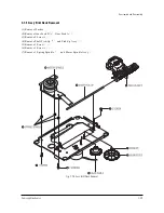
3-7-3 Housing Ass’y Removal
(1) Remove Belt .
(2) Push the Hook in the direction arrow “A” and lift up Pulley Gear .
(3) Push the Slider Housing in the direction arrow “B” and lift up the Gear Tray .
(4) Lift up the Slider Housing .
(5) Remove the soldering of 2 points (Red, Black).
(6) Remove 2 Screws and lift dowm the Motor Load Assy .
(7) Push the 3 Hooks bottom side in the direction arrow “C” and lift up the Housing PCB .
(8) Push the Hooks and remove Deck PCB .
Fig. 3-7-3 Housing Ass’y Removal
"C"
"C"
"C"
Summary of Contents for CFTD2083TX/SMS
Page 2: ...ELECTRONICS Samsung Electronics Co Ltd JULY 2002 Printed in Korea AA82 00093A ...
Page 9: ...Samsung Electronics 3 1 2 Specifications ...
Page 10: ...MEMO 3 2 Samsung Electronics ...
Page 91: ...8 4 Samsung Electronics MEMO ...
Page 92: ...Schematic Diagrams 9 1 Samsung Electronics 9 1 MAIN 1 9 Schematic Diagrams ...
Page 93: ...Schematic Diagrams Samsung Electronics 9 2 9 2 MAIN 2 ...
Page 94: ...Schematic Diagrams Samsung Electronics 9 3 9 3 MAIN 3 ...
Page 95: ...Schematic Diagrams 9 4 Samsung Electronics 9 4 MAIN 4 ...
Page 96: ...Schematic Diagrams 9 5 Samsung Electronics 9 5 POWER BLOCK ...
Page 97: ...Schematic Diagrams 9 6 Samsung Electronics 9 6 DEFLECTION BLOCK ...
Page 98: ...Schematic Diagrams 9 7 Samsung Electronics 9 7 INTERFACE BLOCK ...
Page 99: ...Schematic Diagrams 9 8 Samsung Electronics 9 8 CRT BLOCK ...
Page 100: ...Schematic Diagrams 9 9 Samsung Electronics 9 9 Main Micom ...
Page 101: ...Schematic Diagrams 9 10 Samsung Electronics 9 10 AV Decoder ...


