Disassembly and Reassembly
3-12
Samsung Electronics
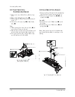
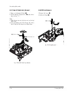
3-3-11 Lever Tension Ass’y,
Band Brake Ass’y Removal
1) Remove the Lever Brake S Ass'y (Refer to Fig
3-17).
2) Remove the Spring Tension Lever
Œ
.
3) Rotate stopper of Main Base in the direction of
arrow “A”.
4) Lift the Lever Tension Ass'y
´
& Band brake
Ass'y
ˇ
.
Note
:
1) When replacing the Lever Tension Ass'y
´
, be
sure to apply Grease on the post,
2) Take care not to touch stain on the felt side, and
not to be folder and broken Band brake Ass'y
3) After Lever Tension Ass'y seated, Rotate stop-
per of Main Base to the Mark[B].
Œ
SPRING TENTION LEVER
STOPPER
MARK[B]
"A"
´
LEVER TENTION ASS`Y
ˇ
BAND BRAKE ASS`Y
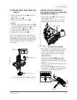
3-3-12 Lever Brake S, T Ass’y Removal
1) Release the Hook [A] and the Hook [B], [C] in
the direction of arrow as shown in Fig 3-17.
2) Lift the Lever S, T Brake Ass'y
Œ
,
´
with
spring brake
ˇ
.
Assembly
:
1)Assembly the Lever S Brake Ass'y
Œ
on the
Main Base.
2)Assembly the Lever T Brake Ass'y
´
with
spring brake
ˇ
.
Note
: Take extreme care not to be folded and
transformed Spring Brake at removing or rein-
stalling.
Œ
LEVER S BRAKE ASS`Y
´
LEVER T BRAKE ASS`Y
ˇ
SPRING BRAKE
HOOK(B)
HOOK(C)
HOOK(A)
Fig. 3-16 Lever Tension Ass’y,
Band Brake Ass’y Removal
Fig. 3-17 Lever Brake S, T Ass’y Removal
Summary of Contents for CFTD2083TX/SMS
Page 2: ...ELECTRONICS Samsung Electronics Co Ltd JULY 2002 Printed in Korea AA82 00093A ...
Page 9: ...Samsung Electronics 3 1 2 Specifications ...
Page 10: ...MEMO 3 2 Samsung Electronics ...
Page 91: ...8 4 Samsung Electronics MEMO ...
Page 92: ...Schematic Diagrams 9 1 Samsung Electronics 9 1 MAIN 1 9 Schematic Diagrams ...
Page 93: ...Schematic Diagrams Samsung Electronics 9 2 9 2 MAIN 2 ...
Page 94: ...Schematic Diagrams Samsung Electronics 9 3 9 3 MAIN 3 ...
Page 95: ...Schematic Diagrams 9 4 Samsung Electronics 9 4 MAIN 4 ...
Page 96: ...Schematic Diagrams 9 5 Samsung Electronics 9 5 POWER BLOCK ...
Page 97: ...Schematic Diagrams 9 6 Samsung Electronics 9 6 DEFLECTION BLOCK ...
Page 98: ...Schematic Diagrams 9 7 Samsung Electronics 9 7 INTERFACE BLOCK ...
Page 99: ...Schematic Diagrams 9 8 Samsung Electronics 9 8 CRT BLOCK ...
Page 100: ...Schematic Diagrams 9 9 Samsung Electronics 9 9 Main Micom ...
Page 101: ...Schematic Diagrams 9 10 Samsung Electronics 9 10 AV Decoder ...


